What Really Happened at the Oroville Dam Spillway?
[edit] The Oroville Dam: A critical structure for Northern California and its complex features
In February 2017, the Oroville Dam experienced a crisis when concrete slabs in the spillway failed during floodgate releases, leading to the evacuation of nearly 200,000 people downstream. Despite being the tallest dam in the United States and falling under the Federal Energy Regulatory Commission’s supervision, this critical incident raised questions about the dam’s safety and maintenance. Fortunately, an independent forensics team conducted an extensive investigation and produced a 600-page report to uncover the cause of the failure. The Oroville Dam, situated in Northern California, stands at an impressive height of 235 meters (770 feet) and serves as a crucial structure for the region.
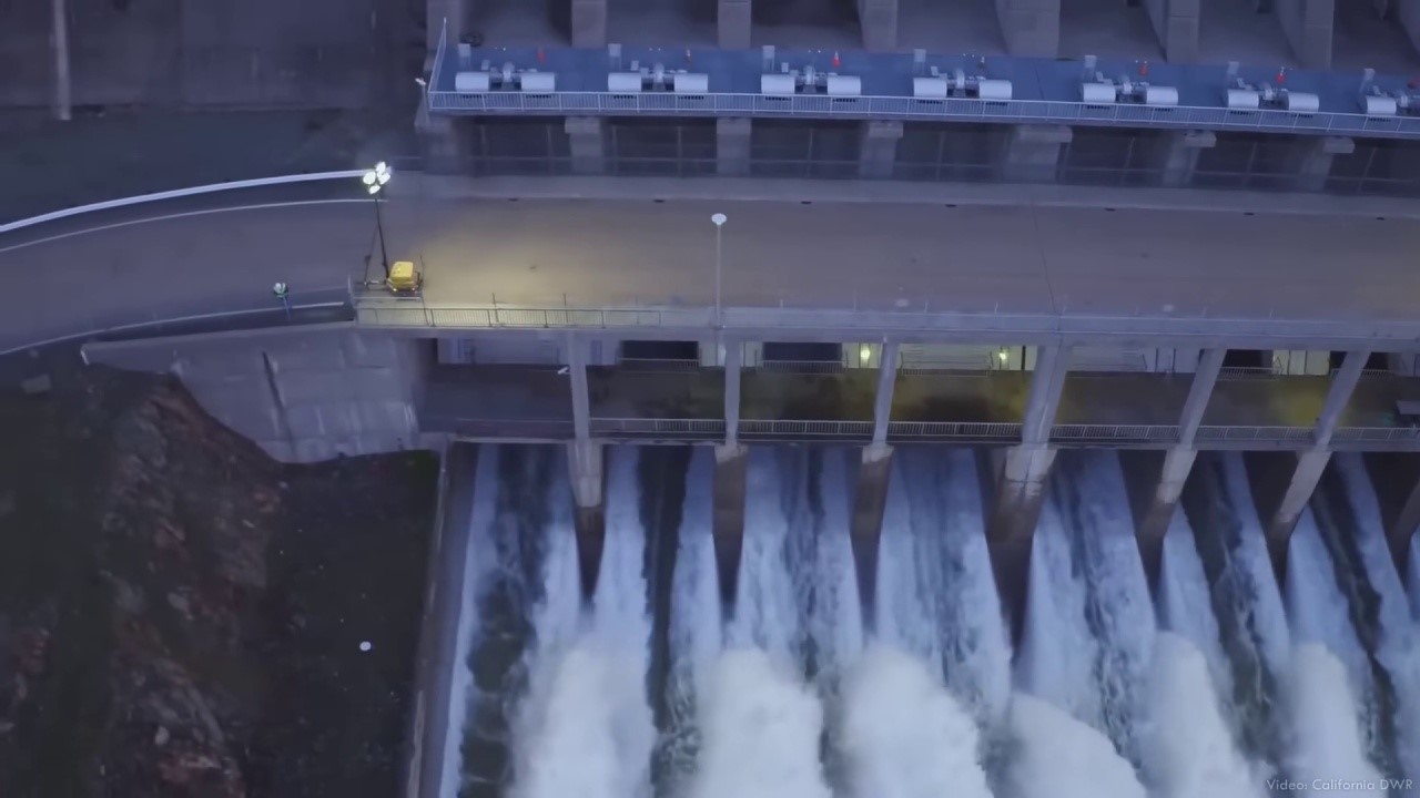
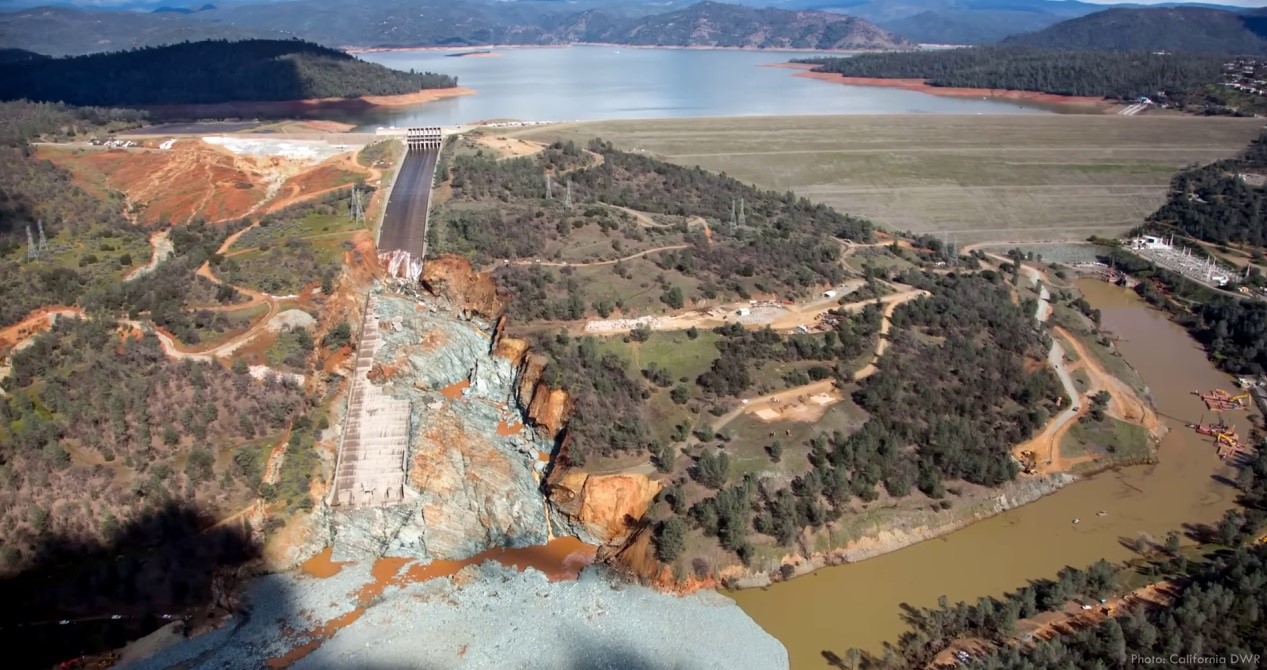
The Oroville Dam, completed in 1968 and managed by the California Department of Water Resources, is a colossal structure. It features an earthen embankment forming the dam, a hydropower generation plant with reversible pump storage, a service spillway equipped with eight radial floodgates, and an emergency overflow spillway. The dam creates Lake Oroville, the second largest reservoir in California, and is an integral part of the California State Water Project. This extensive water storage and delivery system provides water to over 20 million people and vast areas of irrigated farmland.
The reservoir serves multiple purposes, including generating electricity with a capacity of over 800 megawatts. Additionally, during the wet season, the dam maintains an empty reserve volume to store floodwaters in case of significant upstream flooding. This stored water is then gradually released, minimising potential damage downstream. It’s important to note that no dam is designed to hold all the water that could flow into the reservoir at once. To prevent breaches and failures due to water overtopping unprotected embankments, all dams require spillways to safely release excess inflows and maintain the reservoir level once full.
[edit] The intricate design and functionality of Oroville Dam’s spillways
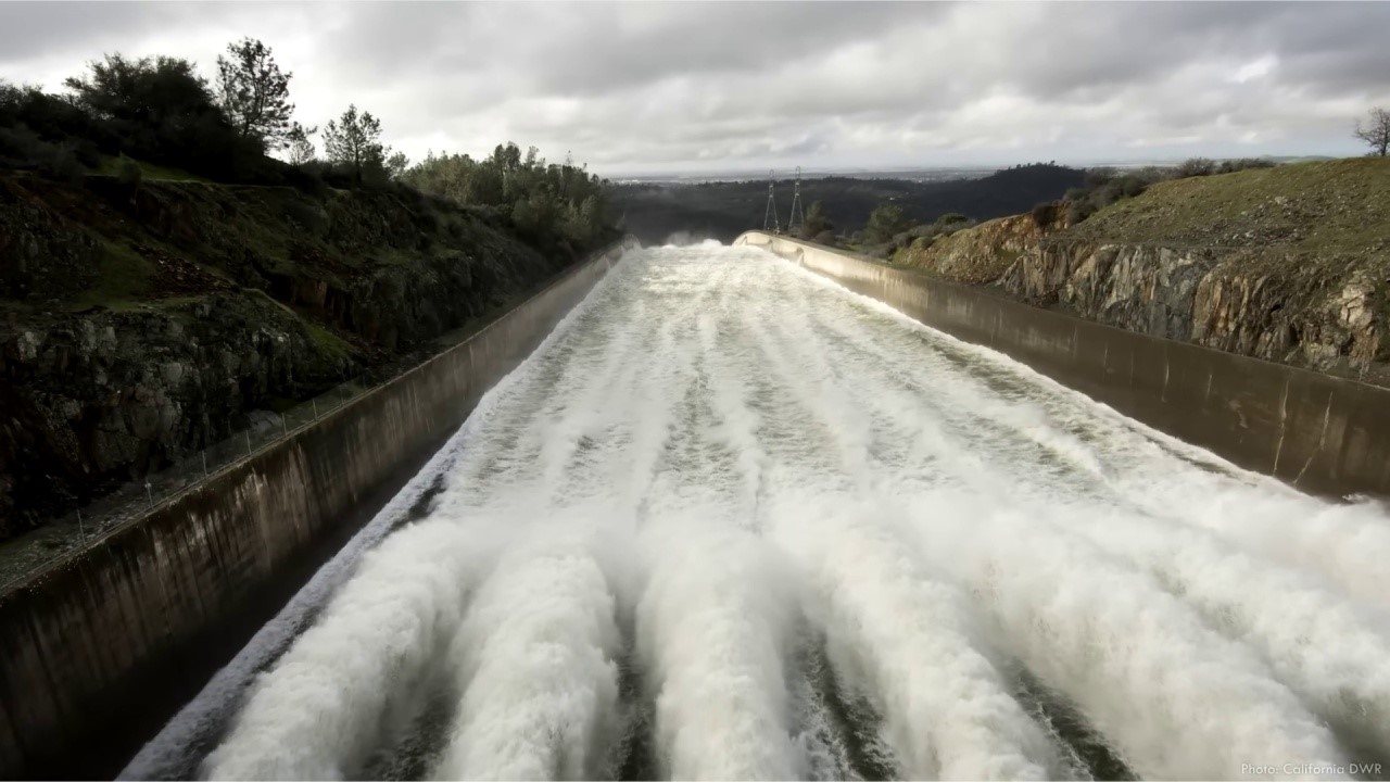
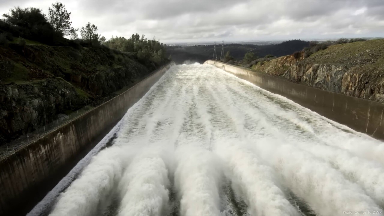
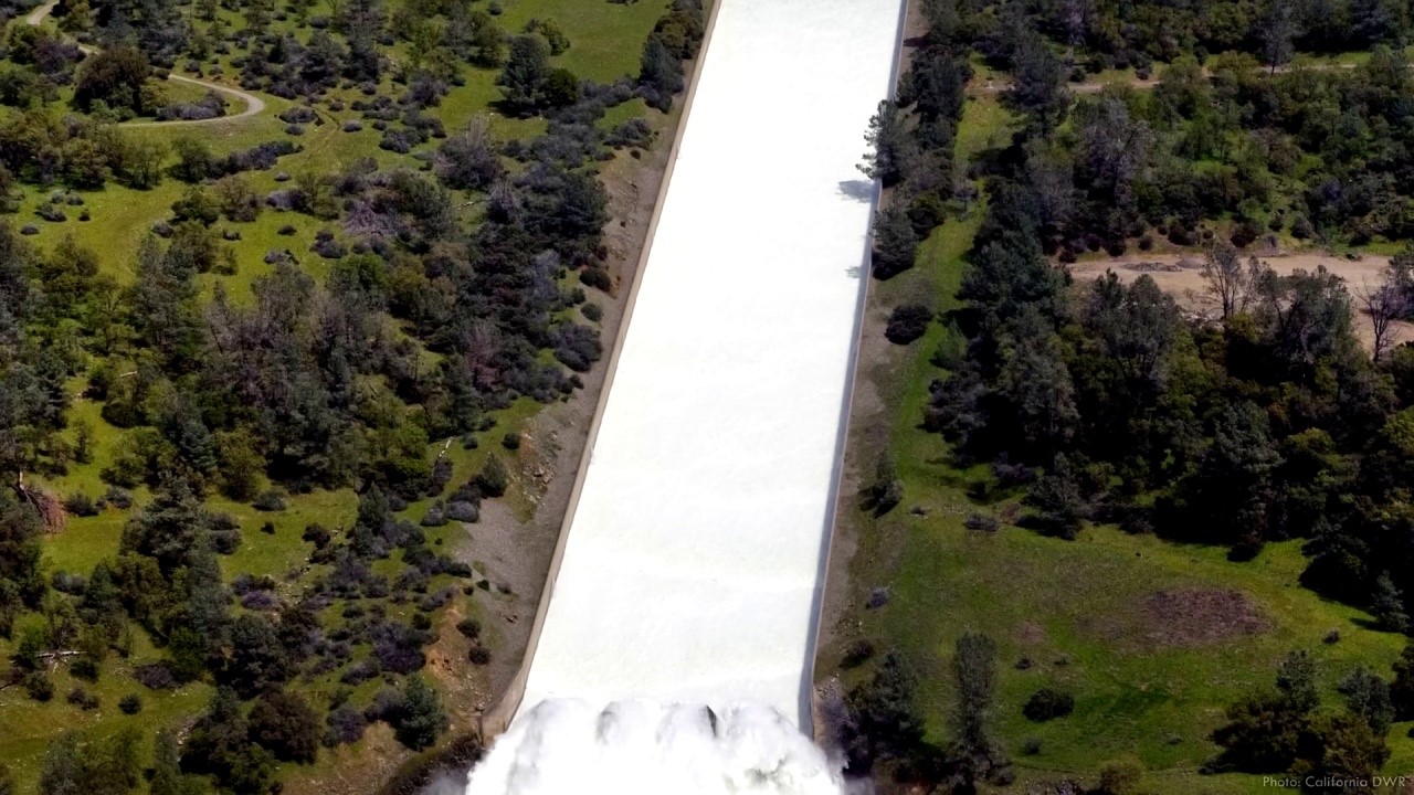
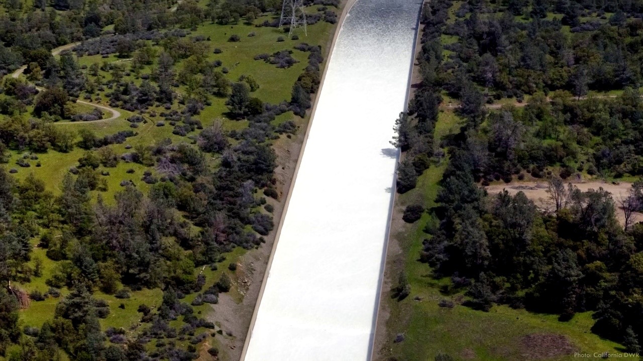
Spillways, like the one at Oroville, can be the most complex and costly components of a dam. Oroville’s service spillway features a 55-metres (180-foot) wide chute that stretches for nearly a kilometre or 3,000 feet. Radial gates manage the water release, while large concrete blocks called dentates at the chute’s base disperse the flow to minimise erosion when it reaches the Feather River. The spillway can release an impressive 8,000 cubic metres (300,000 cubic feet) of water per second, which is equivalent to an Olympic-sized swimming pool every two seconds. To help visualise this immense flow rate, if you were to channel it through a standard garden hose, the water would move at 15% the speed of light and reach the moon in roughly 9 seconds. However, even this impressive flow rate isn’t enough to safeguard the embankment.
Large dams are designed to withstand extraordinary flooding events, often using a synthetic storm called the probable maximum flood as a basis. This storm represents the maximum rainfall that could physically occur. However, designing the primary spillway to handle such an event is often impractical due to its low likelihood of occurring during the dam’s lifetime. Instead, many dams feature a secondary, simpler, and less expensive spillway to handle massive water discharge during rare but extreme events. For example, Oroville Dam has an emergency spillway with a concrete weir set one foot above the maximum operating level.
[edit] Oroville Dam crisis: Balancing spillway damage, flood risks, and power plant operations
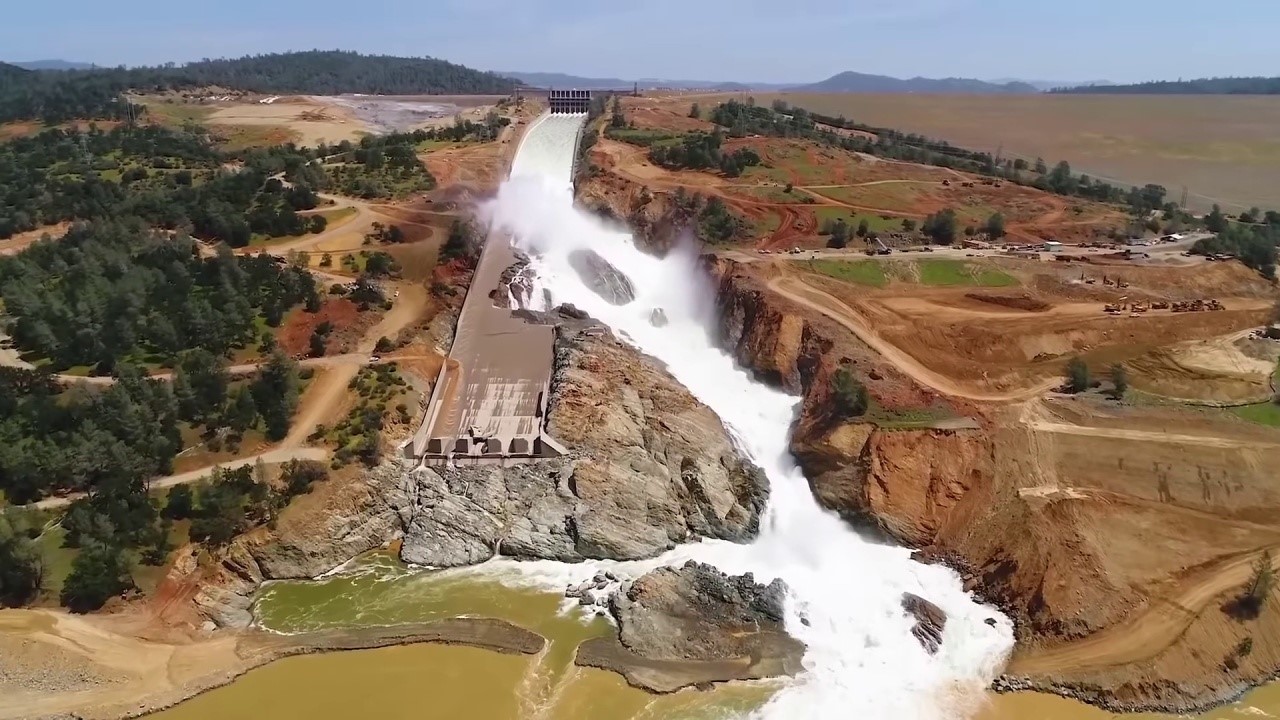
The reservoir overflow system is designed to prevent water from overtopping the dam’s crest by releasing excess water when the service spillway can’t keep up. In early 2017, Northern California experienced one of its wettest winters, leading to several major flood events. One such event occurred in February upstream of Oroville Dam, causing the reservoir to fill rapidly. Operators quickly realised that they needed to open the spillway gates to release the excess inflows. However, on February 7th, they observed an unexpected flow pattern halfway down the chute.
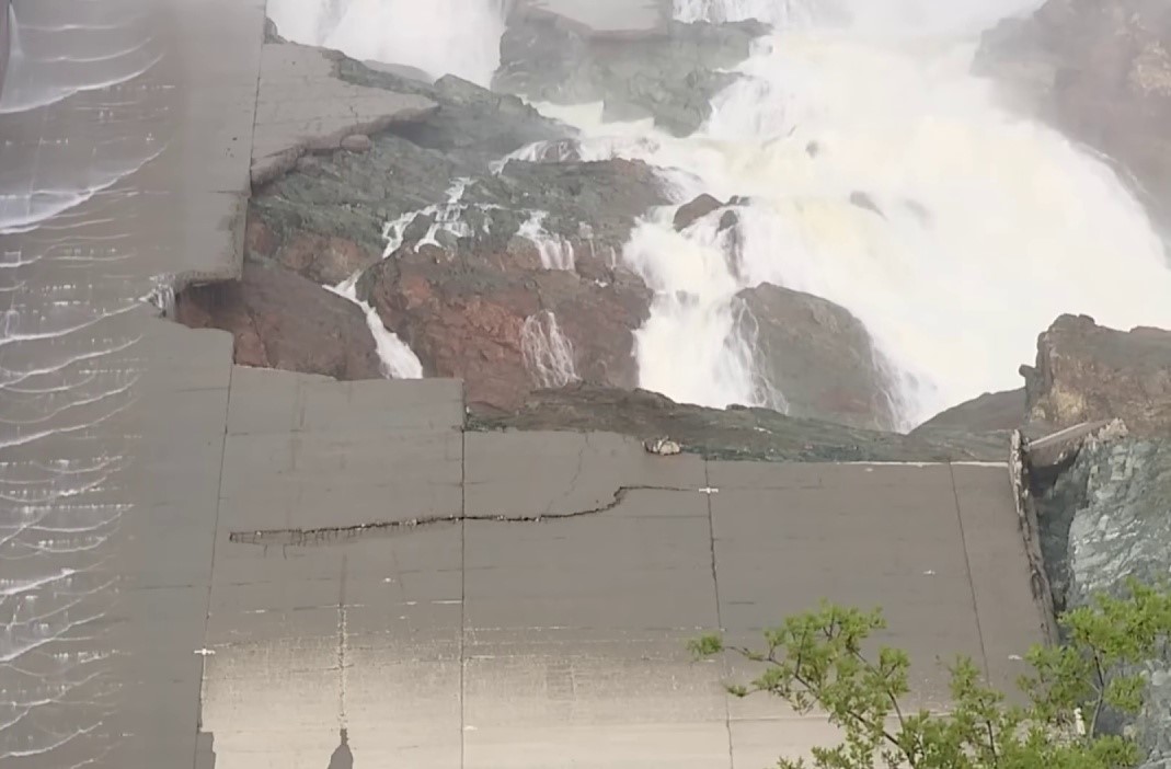
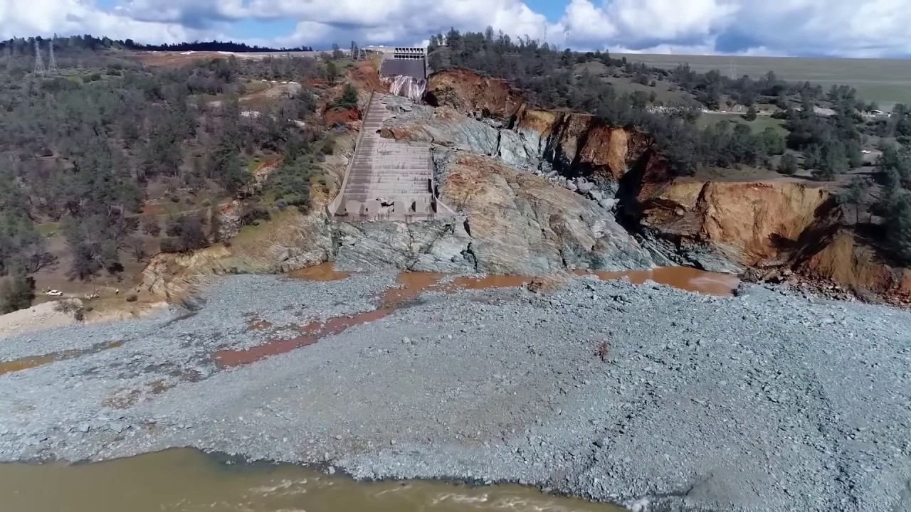
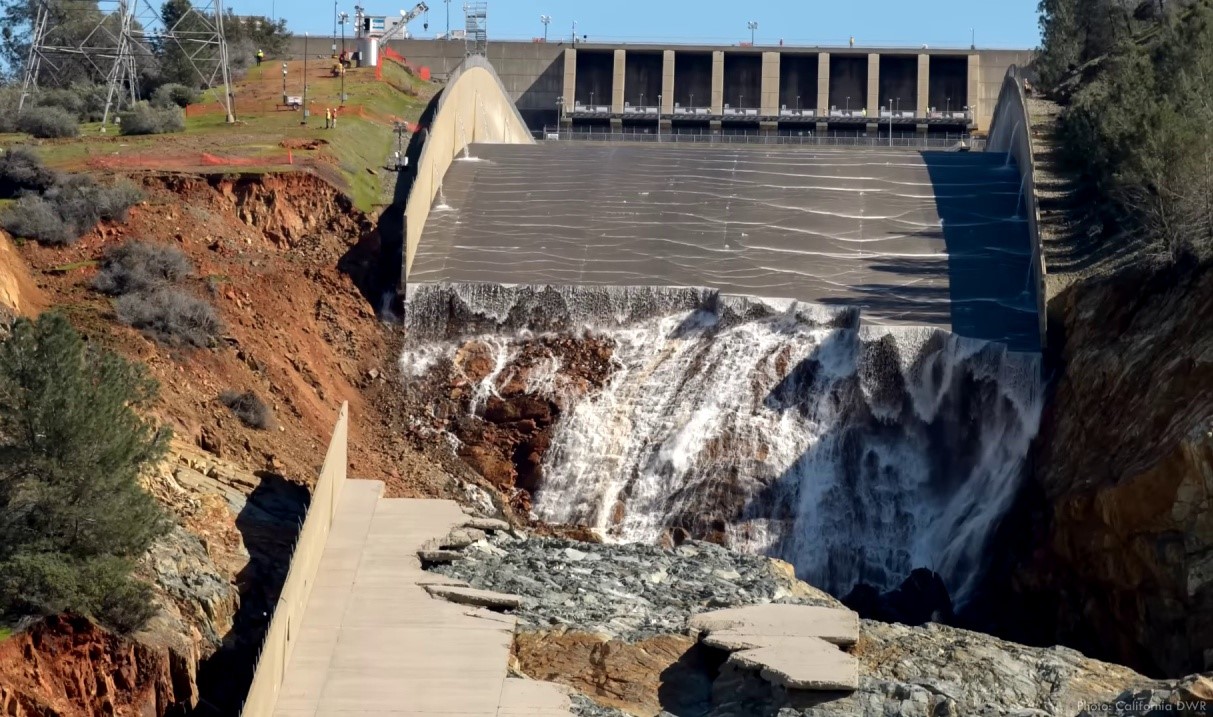
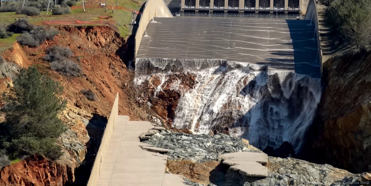
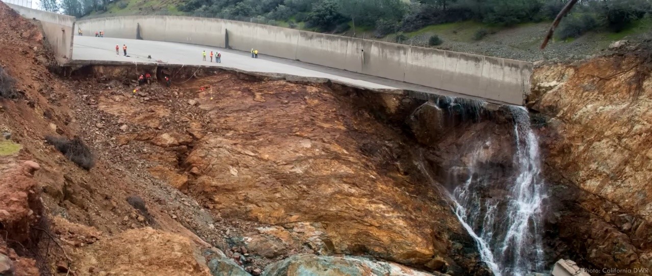
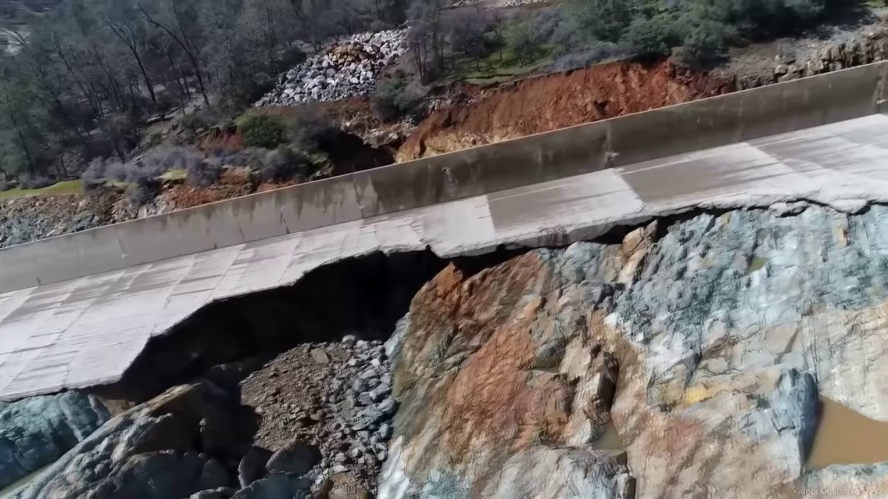
When the situation became alarming, the decision was made to close the gates and halt the flood releases to inspect the damage. Upon stopping the water, they discovered several large concrete slabs missing and a massive hole eroded beneath the chute. With more inflow predicted for the reservoir, there was little time for inspection and no opportunity for repairs. The damaged spillway had to remain operational, so gates were opened incrementally to monitor erosion. As more rain fell upstream, inflows increased, and the reservoir’s level rose rapidly. Operators soon faced a tough choice: open additional gates on the service spillway, risking further damage, or allow the reservoir to overflow the untested emergency spillway and pour down the nearby hillside.
Several factors made the situation more complex. Firstly, the service spillway was in poor condition, leading to concerns about erosion progressing upstream towards the head-works and potentially causing an uncontrolled reservoir release. Secondly, debris from the damaged spillway accumulated in the Feather River, elevating its level and posing a flood risk to the power plant. Lastly, the erosion along the service spillway endangered electrical transmission lines connecting the power plant to the grid. If these lines were lost or the hydropower facility flooded, it would compromise the dam’s only backup for reservoir releases.
Repairing the spillway was deemed nearly impossible until the power plant could be restored, leading operators to consider closing the spillway gates and allowing the reservoir to rise. However, they faced a dilemma: the emergency spillway had never been tested, and there was a lack of confidence in its ability to safely release such a large volume of water. Observing the rapid and aggressive erosion on the nearby service spillway only heightened these concerns. Additionally, using the emergency spillway would likely strip the topsoil and vegetation from the entire hillside, potentially endangering adjacent electrical transmission towers. As a result, a large team of engineers and operations personnel were actively engaged in analysing data, forecasting weather, reviewing geologic records, and examining original design reports to determine the most appropriate course of action.
[edit] Managing a Dam Crisis: Balancing unfavourable options and addressing geological challenges
Over just a few days, operators faced constantly changing conditions and sleep deprivation, making it challenging to manage risks associated with the dam. They aimed to limit releases from the service spillway while preventing the reservoir from overtopping the emergency spillway. However, with each new forecast predicting more rain and inflows, it became evident that they had to choose between two unfavourable options: increasing discharges to flood the powerhouse or allowing the reservoir to rise above the emergency spillway. Ultimately, they opted to let the reservoir level increase.
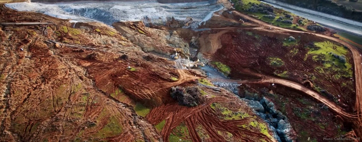
On February 11th, Lake Oroville experienced water rising above the emergency spillway’s crest for the first time in its history, just four days after the initial damage was observed. However, the situation quickly deteriorated as water flowing across the natural hillside began to channelise and concentrate. This rapid acceleration in erosion led to the formation of head-cuts, which indicate unstable and incising waterways. Characterised by vertical drops in topography caused by flowing water, head-cuts consistently move upstream, often at an aggressive pace.
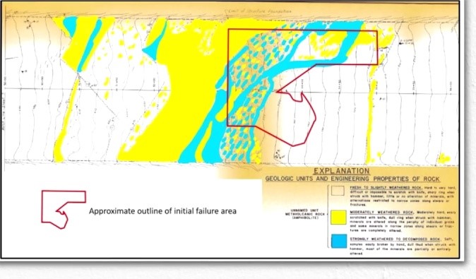
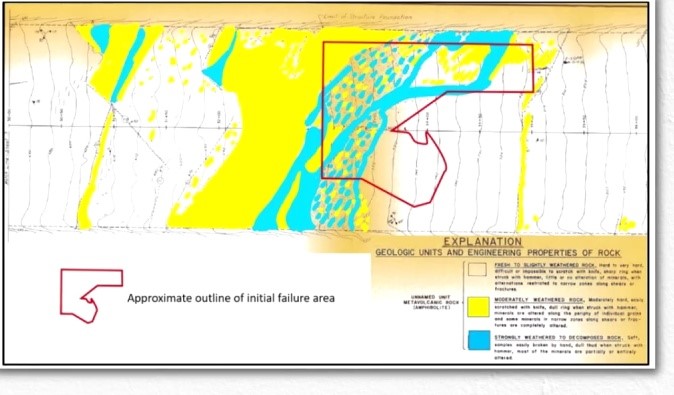
Upstream in this context refers to the direction towards the emergency spillway structure, which was at risk due to the hillside’s unstable composition. The hillside, previously believed to be solid bedrock, was actually made up of erodable soil and weathered rock. If the head-cuts reached the concrete structure, it would likely fail and release a massive wave of water from Oroville Lake, causing destruction in downstream communities.
Realising the urgency of the situation, authorities issued an evacuation order for downstream residents on February 12th, displacing almost 200,000 people. Simultaneously, operators decided to open the service spillway gates, doubling the flow rate to quickly lower the reservoir’s level. The water level dropped below the emergency spillway crest that night, halting the flow and reducing the risk of immediate failure. By February 14th, the evacuation order was downgraded to a warning, allowing residents to return home.
Despite the forecast of more rain, the emergency spillway was not in good shape to manage additional water flow if the reservoir levels increased. The California Department of Water Resources (DWR) maintained discharges through the damaged service spillway to reduce the reservoir by 15 meters (50 feet), creating enough storage space to allow for spillway evaluation and repairs. The gates remained open until February 27th, almost three weeks since the beginning of the crisis, exposing the extensive damage to the dam’s right abutment.
Water begins its journey as minuscule raindrops during a heavy storm, and the earth’s topography funnels and concentrates it. This water is then turbulently released through massive human-made structures, resulting in harrowing scars carved through the hillside. But what causes this phenomenon? Several problems and issues contribute to the failure of concrete chutes, with geology being one of the most fundamental factors.
Despite the knowledge that certain areas of the spillway’s foundation consisted of weathered rock and soil, it was designed and maintained as though the entire structure was built on solid bedrock. This mis-characterisation resulted in significant consequences. The initial damage to the spillway can be attributed to uplift forces.
[edit] Water-induced instability in concrete structures: The Oroville Dam case study
Concrete structures primarily maintain their stability due to their heavy weight, which keeps them anchored to the ground and helps them resist external forces. However, water can introduce complications to this stability. One might assume that adding water on top of a concrete slab would simply increase its weight and stability, but this is not the case when cracks and joints are present.
The Oroville Dam service spillway chute faced a significant issue due to numerous cracks and joints. Water penetrated these cracks, leading to the concrete slabs being submerged on all sides, which exacerbated the problem. The reasons behind the formation of these cracks and joints will be discussed further.
Structures underwater are affected by the buoyant force of the water they displace, which counteracts their weight and can destabilise them. Although concrete still sinks underwater, the net force holding the structure in place is only true in static conditions. When water is moving, such as in a spillway, Bernoulli’s principle comes into play.
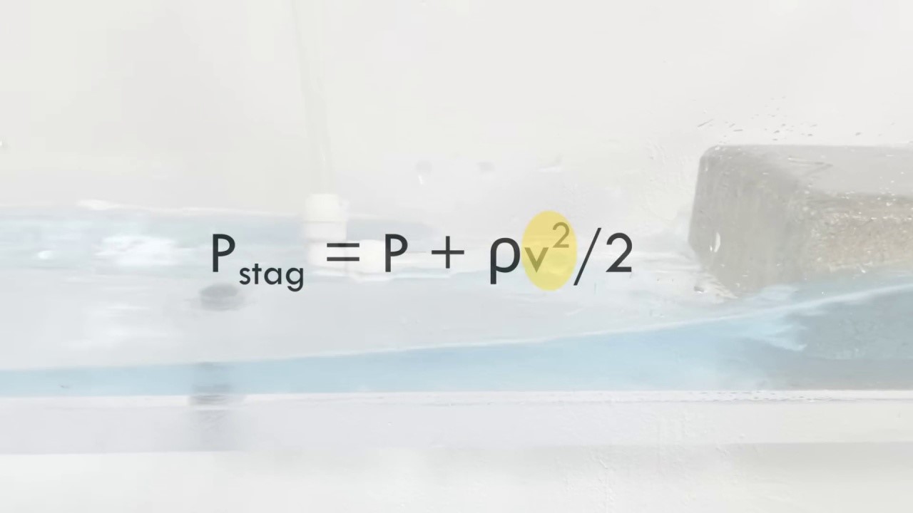
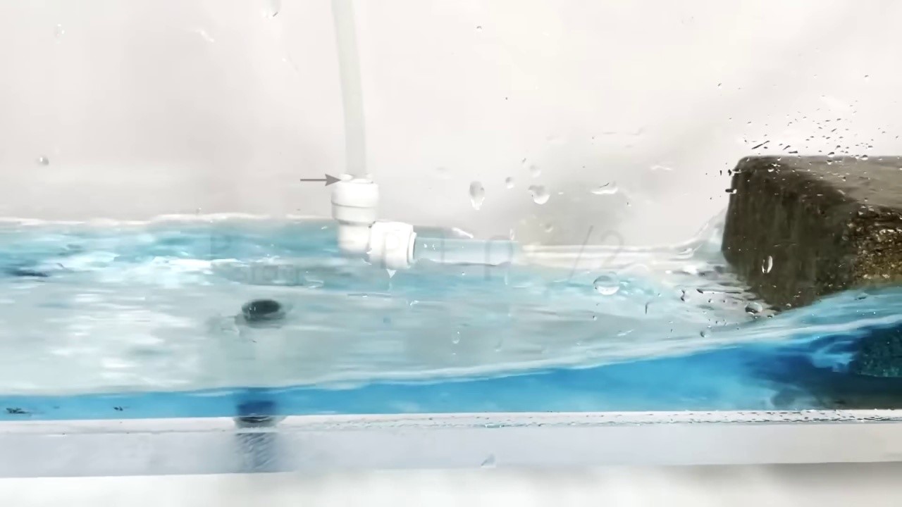
Cracks and joints in a spillway can affect the water flow, and any protrusion into the stream can redirect it. If a joint or crack is offset, the redirection can occur underneath the slab, converting the kinetic energy of the fluid into potential energy or pressure. This is known as stagnation pressure, which occurs when 100% of the kinetic energy is converted. An example of this can be seen when the level rises in a tube directed into flowing water. The equation for stagnation pressure is a function of the velocity squared.
When the speed of the flow in a flume is doubled, the resulting pressure and the height the water rises in the tube are both quadrupled. This is because the pressure is directly proportional to the square of the flow speed. For instance, in the case of the Oroville spillway, the water moves at a significantly higher speed, leading to even greater pressure and water height in the tube.
The stagnation pressure acting on the bottom of a concrete slab generates an additional uplift force. If the total uplift forces surpass the slab’s weight, the slab will move, as seen in the Oroville incident. This causes a chain reaction where more foundation becomes exposed to fast-moving water, allowing the water to seep beneath the slabs and trigger a runaway failure. Engineers attempted to address this issue in the design process.
[edit] Design flaws and human factors: The Oroville Dam spillway incident
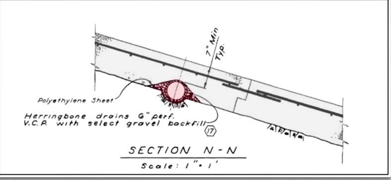
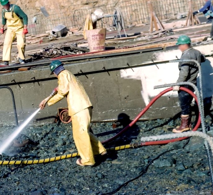
The service spillway featured a drainage system composed of perforated pipes, designed to alleviate the pressure of water flowing beneath the slabs. However, the drain design significantly contributed to the chute cracks. Rather than embedding the drains in trenches within the foundation beneath the slabs, the concrete thickness was reduced to accommodate the drains.
The crack pattern observed on the chute closely resembled the layout of the drains underneath it. This indicated that the drains unintentionally allowed more water to seep below the slab rather than draining it away. Additionally, the chute featured anchors, which were steel rods connecting the concrete to the foundation material. However, these anchors were designed for robust rock foundations, and their design was not adapted when the actual foundation conditions were discovered during construction. Thus, the root cause was not merely a flawed design.
Human factors significantly contributed to the failure to address the inherent weaknesses in large dam structures. Despite regular inspections and periodic design comparisons with current dam engineering practices, issues persisted. Modern spillway designs now incorporate various features to prevent incidents like the one at Oroville. These features include multiple layers of reinforcement to prevent wide cracks, flexible water stops embedded in joints to restrict water migration below the concrete, and keyed joints that prevent slabs from easily separating. Additionally, lateral cutoffs help resist sliding and stop water from moving beneath one slab to another.
Anchors provide uplift resistance by securing slabs to their foundation, and joint surfaces are designed to prevent protrusions in high-velocity water flow. Unfortunately, the Oroville spillway lacked these features or they were improperly executed. Regulators mandated periodic design reviews, which should have identified the deterioration and inherent weaknesses before they escalated into significant problems.
Regarding the emergency spillway, the root issue was a mis-characterisation of the foundation material during and after the design process. Emergency spillways are meant for rare events where some damage may be tolerated, but failure or near-failure putting downstream residents at risk of evacuation is unacceptable. Engineers must make conservative estimates of erosion when an emergency spillway is activated. Predicting erosion caused by flowing water is a challenging task in civil engineering, requiring advanced analysis, and even then, uncertainty remains substantial.
[edit]
Under the intense pressure of an emergency, it can be extremely challenging to make the best decisions. In the case of the dam operators, they opted to let the reservoir rise above the emergency spillway’s crest, instead of increasing discharges through the weakened service spillway. They based this decision on the original designer’s assurance that the structure could handle the increased flow. In retrospect, this decision might not have been the best one, as the powerhouse was farther from flooding and the transmission lines were more secure than initially believed. Eventually, they increased the discharges from the service spillway when they realised the extent of erosion occurring at the emergency spillway.
It’s important to note that the operators, who were making these critical decisions during the crisis, didn’t have the advantage of hindsight. They had to deal with numerous small yet significant decisions made over a long period that contributed to the initial failure. Additionally, the limitations of professional engineering practices can make it difficult to accurately predict outcomes and choose the ideal path.
The forensic team’s report on the Oroville Dam incident offers valuable insights and lessons for dam owners and engineers. One key takeaway is the importance of professional responsibility. People living or working downstream of large dams, like Oroville, often trust engineers, operators, and regulators to ensure their safety without fully understanding the potential risks of dam failure. Unfortunately, in this instance, that trust was broken. This serves as a crucial reminder for professionals whose work impacts public safety. The repair and reconstruction of Oroville Dam’s spillways also present an intriguing subject, possibly explored in future content. Feel free to share your thoughts on this matter.
This article originates from a blog post from May 25, 2023, is based on a Youtube presentation by Practical Engineering, and written by Dr. Costas Sachpazis.
[edit] Related articles on Designing Buildings
- Barrage.
- Building failure.
- Caisson.
- Cascade failure.
- Check dam.
- Consolidation.
- Cracking and building movement.
- Coastal defences.
- Dam construction.
- Dredging.
- Dual purpose reservoirs.
- Flood defences.
- Hydropower.
- Irrigation.
- In Plain Sight: reducing the risk of infrastructure failure.
- Latent defects.
- Mechanisms of structural failure.
- Patent defects.
- Progressive failure.
- Relief well.
- River engineering.
- Spelga dam.
- Structural failures.
- Tidal lagoon power.
- Thames barrier.
- Trading systems for water resources.
- Water engineering.
- Water transfers and interconnections.
Featured articles and news
Guidance notes to prepare for April ERA changes
From the Electrical Contractors' Association Employee Relations team.
Significant changes to be seen from the new ERA in 2026 and 2027, starting on 6 April 2026.
First aid in the modern workplace with St John Ambulance.
Ireland's National Residential Retrofit Plan
Staged initiatives introduced step by step.
Solar panels, pitched roofs and risk of fire spread
60% increase in solar panel fires prompts tests and installation warnings.
Modernising heat networks with Heat interface unit
Why HIUs hold the key to efficiency upgrades.
Reflecting on the work of the CIOB Academy
Looking back on 2025 and where it's going next.
Procurement in construction: Knowledge hub
Brief, overview, key articles and over 1000 more covering procurement.
Sir John Betjeman’s love of Victorian church architecture.
Exchange for Change for UK deposit return scheme
The UK Deposit Management Organisation established to deliver Deposit Return Scheme unveils trading name.
A guide to integrating heat pumps
As the Future Homes Standard approaches Future Homes Hub publishes hints and tips for Architects and Architectural Technologists.
BSR as a standalone body; statements, key roles, context
Statements from key figures in key and changing roles.
ECA launches Welsh Election Manifesto
ECA calls on political parties at 100 day milestone to the Senedd elections.
Resident engagement as the key to successful retrofits
Retrofit is about people, not just buildings, from early starts to beyond handover.
Plastic, recycling and its symbol
Student competition winning, M.C.Esher inspired Möbius strip design symbolising continuity within a finite entity.
Do you take the lead in a circular construction economy?
Help us develop and expand this wiki as a resource for academia and industry alike.
Warm Homes Plan Workforce Taskforce
Risks of undermining UK’s energy transition due to lack of electrotechnical industry representation, says ECA.
Cost Optimal Domestic Electrification CODE
Modelling retrofits only on costs that directly impact the consumer: upfront cost of equipment, energy costs and maintenance costs.









Comments
[edit] To make a comment about this article, click 'Add a comment' above. Separate your comments from any existing comments by inserting a horizontal line.