Ponte della Musica
Contents |
[edit] Ponte della Musica, Roma
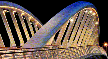
Ponte della Musica is a very shallow arch bridge for pedestrians and cyclists crossing the river Tiber. It is the result of close collaboration between engineer and architect which produced an elegant structure using the highest quality materials, all of which are typical of Rome and have been sourced locally. It’s innovative design uses the springing points of the arch to provide stairs for public access from below the bridge. At a cost of €10.5m it provided excellent value for money for a publicly funded bridge.
The total length of the bridge is almost 190m, comprising a main span of 128m and two side spans of 30m. The bridge comprises two outwardly inclined arches made of tubular, steel-supporting, stiff transverse frames positioned at 8.5m intervals. The arches rise 10.6m above the crown of the deck at midspan, giving a span-to-rise ratio of about 12:1. They are fully fixed at their concrete springing points and support the deck via inclined hangers. The soffit of the bridge deck is 21.6m asl to provide adequate clearance above River Tiber whose average level is 8m asl.
[edit] Competition entry
In 2000, an international design competition was organised by the Comune di Roma (Municipality of Rome) for a new pedestrian bridge to cross the River Tiber in Rome, the first dedicated, large-scale pedestrian bridge to be built over the river since Roman times.
The competition brief called for Ponte della Musica to be a new, flexible, public, open space which can be used for exhibitions, festivals and fairs. It also required that there be no intermediate piers in the river or on the banks, and that while initially built to carry pedestrians, the bridge had to be designed to carry a tram or bus route in the future.
Several structural solutions were proposed including suspension and cable stayed bridges. While cable structures have advantages in terms of flexibility and lightness, the visual intrusion of cables was considered unacceptable in this particular location. The combined requirements for vertical clearance, maximum slopes and the accommodation of tram or bus loading pointed to a shallow arch solution which is both elegant and simple in its effect.
The elegance of the arch is achieved by avoiding the need for bracing; resistance to buckling is achieved using the section of the tube and the stiff U-frames. The simplicity of the structural idea is maintained by through careful detailing of the main connections. At 20m, it is one of the widest pedestrian bridges ever built creating a large area of public realm.
The proposal by Buro Happold and Powell-Williams Architects was the cheapest of the competition entries and was awarded first prize in 2000. The design team was subsequently appointed to develop the scheme design.
[edit] Response to the Brief
The response to the competition brief was a single-flight, shallow arch bridge with inclined arches. Between the main arches a series of frames are suspended, consisting of transverse girders rigidly connected to stiff hangers.
Early sketches and the model made during the competition show how similar the final bridge is to the original concept,. The design team was particular proud to have maintained the bridge's elegant form and details despite the planning and approvals process, two major flood events, protracted contractual negotiations, commercial pressures, the introduction of seismic design requirements and value engineering by the contractors over a period of more than 10 years.
[edit] Materials
The patterns and materials used for the ramps resemble the Parco della Musica, creating an ideal "symmetry" between the opposite ends of Via G. Reni. Particular attention was paid to the integration of the bridge into the landscape. In addition to the main structural materials (steel for the superstructure, concrete for piers, abutments and foundations and timber for decking), the finishing materials and patterns chosen reflect nearby Roman architecture.
[edit] The main arches
The tubular arches are made with constant section to facilitate fabrication and are hermetically sealed to prevent internal corrosion. The 1.25m deep, asymmetric tear-drop shape was chosen to provide adequate stiffness, be aerodynamically efficient, ensure good drainage and for visual interest.
The stiff connection between the deck and the hangers provides “U-frame” restraint to the arches. Longitudinal members provide flexural and torsional stiffness for the bridge deck. The competition scheme had a single 6.6m-wide box girder along the centreline of the bridge, together with two longitudinal box members outside the line of the hangers. The parapets of the bridge were supported by smaller fabricated box sections along the edges of the bridge.
In the end spans, where there is no support from the arches, the longitudinal box girders become the primary structural elements. Either side of the tram pit, a stiffened steel deck plate is provided around the area of the hangers. The cantilevered sections of decking comprise hardwood planks supported on relatively small I- section beams
[edit] Foundations
Finding an efficient solution for the foundations proved to be a challenge because the ground is not particularly good and the arch exerts large horizontal forces. The base input conditions that had to be taken into account in the foundation design were:
- The ground on the site comprises 8-12m of poor made ground (largely loose sandy silts), which overlays a thick stratum of compressible peaty-clayey alluvial deposits up to -50/-55m, where the bedrock is found. The presence of compressible soils between 15m and 50m means this it was not possible to use foundations that apply loads directly in these layers.
- The very shallow shape of the arch produces large horizontal thrusts, equal to approximately twice the vertical loads: the horizontal load on each foundation was estimated equal to 60,000kN.
The solution devised for the first scheme adopted the following approaches:
- Use a "cavalletto" (“trestle”) foundation, clearly separating the reaction to vertical loads, by means of large diameter bored piles reaching the bedrock, from the reaction to horizontal loads. These latter loads are usually dealt with by anchor bolts, but because of the proximity of the river bed this was not possible, and a solution was devised using raked micropiles.
- “Engineer” the ground: instead of adapting the structural and foundation scheme to the existing conditions, the ground could be improved to achieve the minimum geotechnical parameters required by the design. The consolidation was to be executed by mean of jet grouting.
[edit] Design development
Once the contractor was selected a few changes were proposed and subsequently implemented.
[edit] Innovative solution to the foundation problem
During design development, the main contractor proposed a fundamental change to the structural scheme of the bridge, from a true arch to a tied arch, to avoid the inclined mini-piles solution. The design team was reluctant to adopt this proposal which would have meant a radical departure from the competition concept.
Working with the contractor, the design team devised an innovative alternative way of avoiding the use of mini-piles. The load path from the arch is carried through cantilever foundations to provide anchor points for the bridge deck acting as the equilibrating tie. This “self-equilibrating” system eliminated all horizontal thrust on the river banks.
[edit] Changes to the deck design
The design of the deck was changed from the original steel orthotropic construction to a reinforced concrete slab. This had two important benefits for the project:
- The construction method was made less costly. The initial proposal involved constructing the abutments and spring points first, then lifting the arch into place with the internal hangers. The deck units would then be erected on temporary supports in the river. This was changed to supporting the deck units by cables from two towers located on each bank of the river.
- The cost of the bridge was reduced by saving 18% in the weight of steel.
[edit] Statical analysis of structural behaviour
[edit] The basic structural model
The bridge was analysed using LUSAS Finite Element software. This was done by using beam and shell elements, and solid elements for the design of the arch/springing point connection and detailing. Load effects were calculated using the FE program under a multitude of static load combinations derived from standards.
The analysis revealed that the ultimate hangers at each end of the arch were experiencing quite large bending moments and so it was decided to pin the hanger arch connection at these locations to relieve the structure from these large magnitude effects. The connection arrangement was further modified at detailed design stage by adopting a higher-grade steel (460) for that section, to increase the stiffness without changing the cross section.
[edit] Non-linear analysis of the arches
The design of the arch is governed by its susceptibility to out-of-plane bucking. In the non-linear analysis, initial imperfections were introduced into the model to represent construction tolerances that might affect the bucking resistance. This was done by carrying out an eigenvalue buckling analysis and scaling the deformed shape. The resulting geometry was then used as the starting point for the non-linear analysis.
The structural model was initially loaded with 100% dead load and superimposed dead load. Live load was then applied incrementally, and, by plotting deformations against load factor, it was possible to determine the point at which divergent, non-linear, structural behaviour would begin to occur. The structure was considered to have adequate resistance to bucking when its behaviour was still within the linear zone when ultimate loading had been applied to the structure.
[edit] Tram structure analysis
This is one of the extraordinary features of this bridge: the future proofing of the bridge for installation and running of trams. The bridge can accommodate two lanes of fully laden trams end to end for the full length of the bridge and in the middle of the cross section. The tram vehicles were modelled as a set of mechanical systems with many degrees of freedom, linear and non-linear springs and various types of dampers. During their passage, vehicles impose their own weight onto the bridge structure: i.e. the effects of vehicle mass and acceleration. The vehicles affect bridges by imposing spatially oriented forces i.e. vertical forces (wheel or axle force), horizontal longitudinal forces (acceleration and breaking force). When trams were incorporated in the design, special consideration was given to the damping source. The internal source of damping includes viscous internal friction of building materials, experienced during their deformation and their non-homogenous properties. The external source of bridge damping includes friction in supports and bearings, particularly in the ballast, friction in the joints of the structure and aerodynamic resistance.
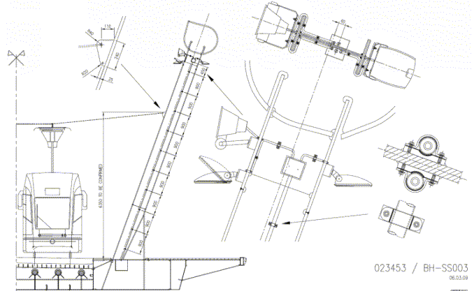
Another feature of the design was inclusion of a derailment devise given that this bridge will have mix use with of trams and pedestrians. The devise is attached adjacent to the running rails.
Trams also impose repetitive loading on the bridge. Structural members, welded and bolted connections are susceptible to fatigue damage caused by this repetitive loading. The design of the bridge was checked against fatigue loading with the consequence that there was an increase in size of the connections
[edit] Dynamic analysis of structural behaviour
[edit] Pedestrian induced loads
To avoid excessive dynamic forces on the bridge and to mitigate pedestrian discomfort, the bridge was examined for its response to human action. The dynamic behaviour of the structure is characterised by its natural frequencies and the mass participation in each of the modes of vibration. For frequencies excited by pedestrian streams it is important to check that the predicted accelerations felt by those on the bridge are within acceptable limits and that potential damage to the structure is avoided. At both the preliminary and definition stages of the design the following analysis was carried out:
- •Vibration modes determined using eigenvalue extraction and separated for further examination (vertical+torsion and horizontal + torsion).
- Interactive modal analysis (IMD) including stationary pulsating loading and moving pulsating loads.
Following changes proposed at the detailed design stage, i.e. an increase in mass resulting from the replacement of the orthotropic plate with composite RC slab and the modification of stiffness of the system after the elimination of the thrust in the arch, a more detailed dynamic analysis was carried out.
[edit] Wind induced loads
Long span footbridges are prone to aerodynamic excitation by wind action. Following assessment of the bridge at the preliminary design stage, which was based on British standard BD49/01, at the definition stag, a more detailed investigation was carried out by wind specialist BMT. This work included the likelihood of aerodynamic excitation based on the dynamic properties of the structure. Recommendations were made about wind tunnel testing which was followed up at the detailed design.
Wind-tunnel testing was undertaken on 1:75 and 1:60 scale models at CRIACIV Laboratory at the University of Florence to determine the mean wind aerodynamic coefficients, and to identify vortex shedding conditions. The design of the bridge was fine-tuned as a result of these tests.
[edit] Seismic analysis
Although not initially a requirement, changes to Italian design regulations during the project required that seismic loading be considered at the definition design stage. The forces imposed on the foundations due to a basic peak ground acceleration of 0.15g (appropriate to a Class III location) were determined and shown to comply with Eurocode 8 (Design Provision for Earthquake Resistance of Structures: Bridges). This was later downgraded to 0.1g, based on updated data and analysis. As seismic effects are not combined with imposed loading, their impact on loading in other structural members was not considered critical.
[edit] Construction, site supervision and inspection
In order to safeguard the concept and scheme design and to ensure continuity, the design team was appointed to carry out the supervision of the works according to national regulations. The works started on site in September 2008 and the foundation works were realised between 2008 and 2009.
The two concrete plinths are 1,620m3 on the right bank and 2,785m3 on the left bank, based on 54 piles, all 55m long. The pile cap on the right bank comprises two overlapping slabs, free to move by means of 27 sliding bearings - in order to allow movement on one of the sides of the bridge, thus releasing any horizontal stresses caused by temperature and live loads.
The steelwork was fabricated by a specialist subcontractor during 2009, preassembled entirely in a fabrication yard, and erected on site during 2010. The steel structure was assembled without the use of temporary piers in the river bed to avoid any interference to the river hydrology during construction. The structure was supported by two temporary towers and a cable-stay system. The main segments (weighting up to 80 tonnes) were launched by a large crane and fully welded on site.
The middle deck section was placed in September 2010, finally connecting the two banks of the river, and the arches were completed in October. In February 2011 the “tie” was prestressed and the temporary towers were removed. The bridge was opened to the public in May 2011.
[edit] Sustainability
The design was modified to improve efficiency in construction and use of materials. An 18% reduction in steel (and carbon footprint) was achieved by opting for a composite bridge as opposed to an orthotropic deck.
The steel, concrete, brick, masonry and asphalt were all sourced locally to reduce the carbon footprint, and ethically-sourced timber (with a low embodied energy) was used for the walkways in the cantilevered sections of the bridge and for the balustrading.
The land under bridges on either side of the bank is landscaped to improve accessibility and quality of fauna under the bridge, improving the environment. The steelwork is fully painted so that it will require minimal maintenance. The bridge has been designed for future tram use, without compromising on its slenderness.
[edit] Value
The cost of construction of the bridge was €10.5m. With a footprint of 400m2, the construction cost was €2,600/m2, making it one of the cheapest pedestrian bridges of significant size in the world. This low cost was achieved by devising a highly efficient design concept and making design changes to reduce the quantity of steel.
The design cost was significantly reduced, and communications with the client were improved, by partnering with Italian consultants (Lotti) based in Rome. This fruitful collaboration paid dividends several times over.
The bridge has had a considerable impact on the area by improving accessibility and providing a destination for visitors, especially in the evenings when the bridge is dramatically illuminated. Since the opening of the bridge, the value of properties in the adjacent residential and commercial buildings has increased by 50%.
This article was created by --Buro Happold.
Featured articles and news
A case study and a warning to would-be developers
Creating four dwellings for people to come home to... after half a century of doing this job, why, oh why, is it so difficult?
Reform of the fire engineering profession
Fire Engineers Advisory Panel: Authoritative Statement, reactions and next steps.
Restoration and renewal of the Palace of Westminster
A complex project of cultural significance from full decant to EMI, opportunities and a potential a way forward.
Apprenticeships and the responsibility we share
Perspectives from the CIOB President as National Apprentice Week comes to a close.
The first line of defence against rain, wind and snow.
Building Safety recap January, 2026
What we missed at the end of last year, and at the start of this...
National Apprenticeship Week 2026, 9-15 Feb
Shining a light on the positive impacts for businesses, their apprentices and the wider economy alike.
Applications and benefits of acoustic flooring
From commercial to retail.
From solid to sprung and ribbed to raised.
Strengthening industry collaboration in Hong Kong
Hong Kong Institute of Construction and The Chartered Institute of Building sign Memorandum of Understanding.
A detailed description from the experts at Cornish Lime.
IHBC planning for growth with corporate plan development
Grow with the Institute by volunteering and CP25 consultation.
Connecting ambition and action for designers and specifiers.
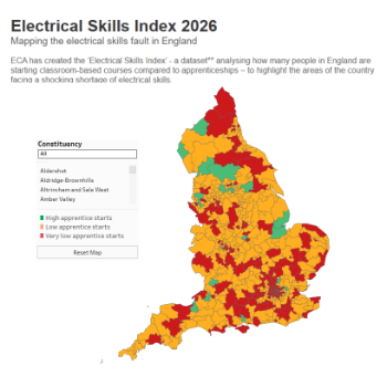
Electrical skills gap deepens as apprenticeship starts fall despite surging demand says ECA.
Built environment bodies deepen joint action on EDI
B.E.Inclusive initiative agree next phase of joint equity, diversity and inclusion (EDI) action plan.
Recognising culture as key to sustainable economic growth
Creative UK Provocation paper: Culture as Growth Infrastructure.
Futurebuild and UK Construction Week London Unite
Creating the UK’s Built Environment Super Event and over 25 other key partnerships.
Welsh and Scottish 2026 elections
Manifestos for the built environment for upcoming same May day elections.
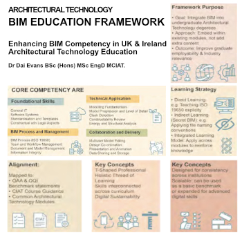
Advancing BIM education with a competency framework
“We don’t need people who can just draw in 3D. We need people who can think in data.”


