Manual drafting techniques
Contents |
[edit] Introduction
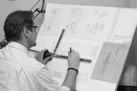
Manual drafting is the practice of creating drawings by hand. Manual drafting techniques have traditionally enabled the planning and communication of design ideas and construction information. As there is a very diverse range of information that may need to be communicated, there are a similarly wide range of drawing types. See Types of drawing for more information.
The evolution of manual drafting techniques has created a discipline around which other forms of drafting, such as computer-aided design (CAD) have subsequently developed.
The advantages of manual drafting include; the low cost of equipment compared to CAD hardware and software, the clarity that can be achieved by being able to see all shapes, sizes and angles on one sheet, the ability to bring creative style and expression to drawings, and a degree of depth and weight that can be easier to convey with 'analogue' rather than 'digital' drawing techniques. Those with experience of manual drafting would agree it gives a much deeper sense of knowledge and understanding of the drawing and then the finished building compared with CAD. Indeed some find it easier to sketch, in pencil, their drawing on paper then produce it on CAD.
However, manual drafting is now becoming something of a lost art, as; it requires a large amount of space, both for the drawing process, storage and viewing; drawings cannot be linked to digital information, they can take much more time to prepare in comparison with CAD drawings, they are more difficult to correct, text and colour can be more difficult to apply, it is more complicated to create three-dimensional representations, with isometric being the most common and a lot of experience is needed to complete a drawing efficiently without wasting too much time.
Those with experience can churn out a drawing just as quickly as a CAD drawing but the effort getting to that level is much higher compared to using CAD. Their is a lot more cost with manual drawings as draughts people would need to be employed.
[edit] Equipment
Manual drafting requires a flat drafting table, drafting or drawing board, typically with a parallel motion, that allows consistent drawing of parallel lines. Drawing boards can often be adjusted in height and angle to suit the user. Typically with light from the north falling on the paper, from top or behind, the board is angled for drawing and flat for tracing. The angle aids in keeping your set square against the sliding ruler (if you needed to draw 90° lines) and helping with good posture.
Vellum paper was used traditionally for drafting and came supplied in rolls. More recently, drafting paper, standard paper sheets, or tracing paper have become more common as they are less expensive.
A range of paper sizes are available suitable for different purposes. See Paper sizes for more information.
Manual drafting tools include:
- Specialised pencils with varying lead hardness.
- 2H & 4H for first drawing and construction lines
- All lines overlap 2 mm to give a sharp corner/joint
- Technical drawing pens of varying sizes (see technical drawing pen sizes for more information).
- Used to overwrite the pencil lines and give permanent lines
- Students could make do with 0.3 and 0.7 pens (holding at different angles to give lighter and thicker lines)
- Colour application pens.
- Scale rules.
- Set squares.
- Adjustable set squares are common.
- T squares.
- Or sliding ruler for boards that hand these fitted.
- Steel rules that are not damaged by being used repeatedly to draw lines.
- Compasses.
- Protractors.
- Dividers.
- Drafting tape, masking tape (3M Magic removable tape and glue dots work well too) or stainless steel clips to secure the corners of the sheet to the board.
- Fixed in line with the paper, not angled over the corners as an amateur would do, damaging the corners.
- Pencil sharpeners.
- Erasers.
- Pen cleaners.
- Scalpel blades for:
- Clear tape for repairing drawings (this does not show on reproductions)
- Mechanical lead holders for using various size leads for different parts of the draft.
- Templates or stencils allowing easy drawing of certain objects, symbols, common shapes, text, and so on.
- Text writing machines.
- Letraset lettering sheets that can be applied to drawings as a form of transfer. Other sheets include people, trees and other common objects and symbols.
- Pantone colour and greyscale sheets than can be cut and applied to drawings to bock colour or shade areas.
- Correction fluid - Tipex (which does not show on reproductions).
- Tape and correction pens work well too
- Drawing board attachments that can be fixed to the parallel motion ruler to create specific angles, reproduce lines or change scales.
[edit] Lines
Lines in manual drafts should be clean and sharp. A straight edge should always be used when manually drafting. A parallel motion, or T-square can be used to draw horizontal lines, and a T-square or set square to draw vertical lines or other common angles.
Typically, the bottom of the set square is placed on the top of the parallel motion, and the vertical portion used to draw straight lines. To draw a vertical line using a T-square, the T portion should be placed flat against the top of the drawing board.
Equal pressure should be applied on the pen or pencil when drawing lines, slightly rotating the point, and not removing it from the paper until the line is completed.
Sprinkling setting powder, or using fixing sprays over pencil lines can help maintain the integrity of the lines when the sheets are folded or rolled, or otherwise brushed against.
[edit] Line weights
Manual drafting techniques typically involve drawing different line weights to represent different items. Different line weights can be created by using a different size mechanical pencil lead, or a different size of technical drawing pen.
Exterior walls are typically drawn on floor plans and sections with heavy, solid lines. Windows may be drawn lighter, or with the same heaviness but in a dash-dot-dash format. Interior walls have slightly lighter line weights. Elements such as fittings should be drawn with the lightest line weight, and sometimes dashed lines.
[edit] Lettering
It is important to maintain correct lettering sizes in manual draft, for example:
- Notes: 3/32 inch letters.
- Special notes: 1/8 inch letters.
- Titles: 1/4 inch letters.
F pencils or technical drawing pens are typically used for lettering, with a small right triangle to draw straight portions of the letter. Curved portions may be drawn freehand. Thicker strokes are used for horizontal lines, thinner strokes for vertical lines. It can be useful to draw light guidelines first to ensure the correct and uniform text height.
This is a carefully practiced skill and Frank Chings book "Architectural graphics" shows practice papers of the kind primary school children use to get the lettering right. Alternatively just writing 4 mm x 4 mm capital letters looks right for most manual drawings.
Alternatively, stencils, transfers or writing machines may be used.
[edit] Scale
The use of different scales enables objects and spaces to be depicted at a specific ratio to their actual size, helping to maintain consistency. Suitable scales will vary depending on the size of object, size of paper and level of information that needs to be conveyed, however, floor plans are commonly drawn with a 1/4 inch = 1 foot or 1:50 scale, kitchens and bathrooms with a 1/2 inch = 1 foot or 1:20 scale, wall sections with a 3/4 inch= 1 foot or 1:10 scale and so on.
[edit] Projections
There are a number of techniques of projection that can be used to represent three-dimensional objects in two-dimensions by 'projecting' their image onto a planar surface.
See Drawing projections for more information.
[edit] Notation and units
Standard notation conventions should be followed so that there is clear communication between different people and mistakes are avoided.
See Notation and units for more information.
[edit] Symbols
A range of standard symbols and hatching techniques can be used to convey recognised meaning without the need for explanation.
See Symbols on architectural drawings for more information.
[edit] CAD and BIM
Since the 1980s, computer aided design (or computer aided drafting), and more recently, building information modelling have transformed drafting techniques, in particular allowing alterations to be made with relative ease.
Many companies and institutions will have scanned their hand drawn copies into computers and digitised these, and the original drawings will be kept in a locked drawing cabinet in an archive room that is secure.
Parametric modelling allows the 'automatic' creation of aspects of drawings based on a series of pre-programmed rules. So, for example, a rule might be created to ensure that walls must start at floor level and reach the underside of the ceiling. Then if the floor to ceiling height is changed, the walls will automatically adjust to suit. Other examples might include the colour of similar elements, the height of windowsills above floor level, the relationship between walls and a pitched roof, and so on.
See CAD, BIM and parametric modelling for more information.
[edit] Related articles on Designing Buildings
- Architectural reprography.
- Blueprint.
- Common mistakes on building drawings.
- Drawing board.
- Drawing projections.
- Elevations.
- Engineering drawing.
- General arrangement drawing.
- How to draw a floor plan.
- Notation and units.
- Paper sizes.
- Parallel motion.
- Perspective.
- Scale.
- Scale drawing.
- Scale rule.
- Standard hatching styles for drawings.
- Symbols on architectural drawings.
- T-square.
- Technical drawing pen sizes.
- Techniques for drawing buildings.
- Types of drawings.
- Visualisation.
Featured articles and news
Welsh and Scottish 2026 elections
Manifestos for the built environment for upcoming same May day elections.
Advancing BIM education with a competency framework
“We don’t need people who can just draw in 3D. We need people who can think in data.”
Guidance notes to prepare for April ERA changes
From the Electrical Contractors' Association Employee Relations team.
Significant changes to be seen from the new ERA in 2026 and 2027, starting on 6 April 2026.
First aid in the modern workplace with St John Ambulance.
Ireland's National Residential Retrofit Plan
Staged initiatives introduced step by step.
Solar panels, pitched roofs and risk of fire spread
60% increase in solar panel fires prompts tests and installation warnings.
Modernising heat networks with Heat interface unit
Why HIUs hold the key to efficiency upgrades.
Reflecting on the work of the CIOB Academy
Looking back on 2025 and where it's going next.
Procurement in construction: Knowledge hub
Brief, overview, key articles and over 1000 more covering procurement.
Sir John Betjeman’s love of Victorian church architecture.
Exchange for Change for UK deposit return scheme
The UK Deposit Management Organisation established to deliver Deposit Return Scheme unveils trading name.
A guide to integrating heat pumps
As the Future Homes Standard approaches Future Homes Hub publishes hints and tips for Architects and Architectural Technologists.
BSR as a standalone body; statements, key roles, context
Statements from key figures in key and changing roles.
Resident engagement as the key to successful retrofits
Retrofit is about people, not just buildings, from early starts to beyond handover.














Comments