


General arrangement drawing

[edit] What are general arrangement drawings?
General arrangement drawings (GA’s) present the overall composition of an object such as a building. This is as opposed to more detailed drawings such as component drawings or assembly drawings that might only show a particular aspect or part of the object. General arrangement drawings show how the components fit together to create the whole.
Depending on the complexity of the building, they are likely to include a number of different projections, such as plans, sections and elevations, and the complete information may be spread across several different drawings. They may also be referred to as 'location drawings' as they show the location of various components and assemblies within the overall design, but this can be confused with location drawings indicating the geographical location of the building.
[edit] How are general arrangement drawings prepared?
General arrangement drawings are likely to be prepared at each stage of development of a design, showing the overall relationship between the main elements and the key dimensions. The level of detail will increase as the project progresses and they may need to be supplemented by more detailed drawings, showing specific elements and assemblies. On very simple projects these may be included on the general arrangement drawings themselves, but generally, separate drawings will be required. They can be very large drawings depending on the size and complexity of the obeject being represented and the scale used.
General arrangement drawings may include references to additional information, such as specifications and detail drawings, however they should not duplicate information included elsewhere as this can become contradictory and may cause confusion.
They may include notation, symbols, hatching and so on to indicate additional detail about particular elements. It is important that these are consistent with industry standards so that their precise meaning is clear and can be understood. For more information see: Symbols on architectural drawings.
They may also include other elements, such as a tile block indicating the drawing name and number, the creator of the drawing, the revision number, the scale, a north point and a key.
The scale at which drawings are prepared should reflect the level of detail of the information they are required to convey. Different line thicknesses can also be used to provide greater clarity for certain elements. For more information see: Scale in the construction industry.
General arrangement drawings may be drawn by hand, or prepared using Computer Aided Design (CAD) software. However, increasingly, building information modelling (BIM) is being used to create 3 dimensional representations of buildings and their components. General arrangement drawings can then be generated from the BIM model to the required scale.
BS EN ISO 7519:1997 Technical drawings. Construction drawings. General principles of presentation for general arrangement and assembly drawings establishes the general principles of presentation to be applied to construction drawings for general arrangement and assembly. This standard compliments the ISO 128 series on technical drawings.
[edit] Related articles on Designing Buildings
- As-built drawings and record drawings.
- Assembly drawing.
- Building information modelling.
- Component drawing.
- Computer aided design.
- Design drawings.
- Detail drawing.
- Elevations.
- Engineering drawing.
- Installation drawings.
- Notation and symbols.
- Paper sizes.
- Production information.
- Projections.
- Scale drawing.
- Section drawing.
- Shop drawings.
- Specification.
- Technical drawing.
- Technical drawing pen sizes.
- Working drawing.
Featured articles
Check out some of the best features and news from Designing Buildings as well as key stories from around the web.

Channel 4 broadcaster to host 125th anniversary ceremony.
Listed structures on the rail network
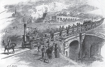
Heritage interests and operational requirements must be balanced.
Historic England publishes research into embodied carbon when retrofitting traditional buildings.

New Prime Minister delivers on ECA call for cut in electricity costs.

CIOB reacts to the announcement of Andy Burnham as Prime Minister.

Heritage and conservation science workforce survey - Have your say.
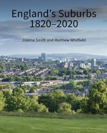
England's Suburbs 1820-2020. Book review.

New, more proportionate and targeted approach for higher-risk building assessments.

Government brings British Steel into public ownership.

UKCW Birmingham returns with bold new theme and focus.

New guidance published on competence requirements for self-certification schemes.
Construction Management, 8 July

NEETs crisis drives interest in trades, but apprenticeships barriers remain.
Comments
[edit] To make a comment about this article, or to suggest changes, click 'Add a comment' above. Separate your comments from any existing comments by inserting a horizontal line.