Detail drawing
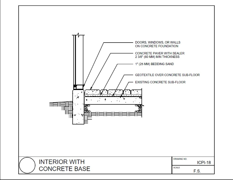
Detail drawings provide a detailed description of the geometric form of a part of an object such as a building, bridge, tunnel, machine, plant, and so on. They tend to be large-scale drawings that show in detail parts that may be included in less detail on general arrangement drawings.
Detail drawings may be used to demonstrate compliance with regulations and other requirements, to provide information about assembly and the junctions between components, to show construction details, detailed form, and so on, that would not be possible to include on more general drawings.
They may include dimensions, tolerances, notation, symbols and specification information, but this should not duplicate information included in separate specifications as this can become contradictory and may cause confusion.
They may consist of two-dimensional orthogonal projections showing plans, sections and elevations and may be drawn to scale by hand, or prepared using Computer Aided Design (CAD) software. However, increasingly, building information modelling (BIM) is being used to create detailed three-dimensional representations of buildings and their components.
Detail drawings may be confused with ‘detailed design drawings’ which might describe the drawings produced during the detailed design stage, (sometimes referred to as 'developed design' or 'definition'). Detailed design is the process developing the design so that it is dimensionally correct and co-ordinated, describing all the main components of the building and how they fit together. Not all drawings produced during this stage will necessarily be detail drawings.
They are also distinct from the definition of ‘working drawings’ which provide dimensioned, graphical information that can be used by a contractor to construct the works, by suppliers to fabricate components of the works or to assemble or install components. Again, not all working drawings will necessarily be detail drawings.
[edit] Related articles on Designing Buildings
- As-built drawings and record drawings.
- Assembly drawing.
- Building information modelling.
- Component drawing.
- Computer aided design.
- Concept drawing.
- Demystifying design processes of architectural details.
- Design drawings.
- Electrical drawing.
- Engineering drawing.
- Exploded view.
- General arrangement drawing.
- Geometric form.
- Installation drawings.
- North American Paper Sizes
- Notation and symbols.
- Packaging.
- Paper sizes.
- Production information.
- Projections.
- Residential design and 3D rendering.
- Scale drawing.
- Section drawing.
- Shop drawings.
- Specification.
- Technical drawing.
- Technical drawing pen sizes
- Working drawings.
Featured articles and news
Building Safety recap January, 2026
What we missed at the end of last year, and at the start of this...
National Apprenticeship Week 2026, 9-15 Feb
Shining a light on the positive impacts for businesses, their apprentices and the wider economy alike.
Applications and benefits of acoustic flooring
From commercial to retail.
From solid to sprung and ribbed to raised.
Strengthening industry collaboration in Hong Kong
Hong Kong Institute of Construction and The Chartered Institute of Building sign Memorandum of Understanding.
A detailed description fron the experts at Cornish Lime.
IHBC planning for growth with corporate plan development
Grow with the Institute by volunteering and CP25 consultation.
Connecting ambition and action for designers and specifiers.
Electrical skills gap deepens as apprenticeship starts fall despite surging demand says ECA.
Built environment bodies deepen joint action on EDI
B.E.Inclusive initiative agree next phase of joint equity, diversity and inclusion (EDI) action plan.
Recognising culture as key to sustainable economic growth
Creative UK Provocation paper: Culture as Growth Infrastructure.
Futurebuild and UK Construction Week London Unite
Creating the UK’s Built Environment Super Event and over 25 other key partnerships.
Welsh and Scottish 2026 elections
Manifestos for the built environment for upcoming same May day elections.
Advancing BIM education with a competency framework
“We don’t need people who can just draw in 3D. We need people who can think in data.”
Guidance notes to prepare for April ERA changes
From the Electrical Contractors' Association Employee Relations team.
Significant changes to be seen from the new ERA in 2026 and 2027, starting on 6 April 2026.
First aid in the modern workplace with St John Ambulance.
Solar panels, pitched roofs and risk of fire spread
60% increase in solar panel fires prompts tests and installation warnings.
Modernising heat networks with Heat interface unit
Why HIUs hold the key to efficiency upgrades.















Comments
what kinds of scales we r using for detail drawings ? metric & architectural
Thank you :)