General arrangement drawing
[edit] What are general arrangement drawings?
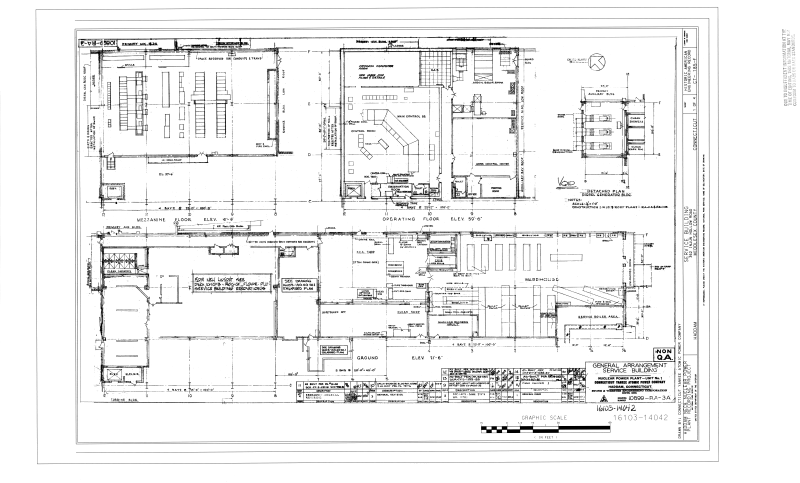
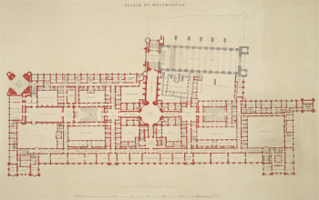
General arrangement drawings (GA’s) present the overall composition of an object such as a building. This is as opposed to more detailed drawings such as component drawings or assembly drawings that might only show a particular aspect or part of the object. General arrangement drawings show how the components fit together to create the whole.
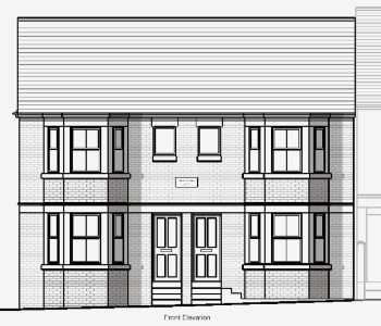
Depending on the complexity of the building, they are likely to include a number of different projections, such as plans, sections and elevations, and the complete information may be spread across several different drawings. They may also be referred to as 'location drawings' as they show the location of various components and assemblies within the overall design, but this can be confused with location drawings indicating the geographical location of the building.
[edit] How are general arrangement drawings prepared?
General arrangement drawings are likely to be prepared at each stage of development of a design, showing the overall relationship between the main elements and the key dimensions. The level of detail will increase as the project progresses and they may need to be supplemented by more detailed drawings, showing specific elements and assemblies. On very simple projects these may be included on the general arrangement drawings themselves, but generally, separate drawings will be required. They can be very large drawings depending on the size and complexity of the obeject being represented and the scale used.
General arrangement drawings may include references to additional information, such as specifications and detail drawings, however they should not duplicate information included elsewhere as this can become contradictory and may cause confusion.
They may include notation, symbols, hatching and so on to indicate additional detail about particular elements. It is important that these are consistent with industry standards so that their precise meaning is clear and can be understood. For more information see: Symbols on architectural drawings.
They may also include other elements, such as a tile block indicating the drawing name and number, the creator of the drawing, the revision number, the scale, a north point and a key.
The scale at which drawings are prepared should reflect the level of detail of the information they are required to convey. Different line thicknesses can also be used to provide greater clarity for certain elements. For more information see: Scale in the construction industry.
General arrangement drawings may be drawn by hand, or prepared using Computer Aided Design (CAD) software. However, increasingly, building information modelling (BIM) is being used to create 3 dimensional representations of buildings and their components. General arrangement drawings can then be generated from the BIM model to the required scale.
BS EN ISO 7519:1997 Technical drawings. Construction drawings. General principles of presentation for general arrangement and assembly drawings establishes the general principles of presentation to be applied to construction drawings for general arrangement and assembly. This standard compliments the ISO 128 series on technical drawings.
[edit] Related articles on Designing Buildings
- As-built drawings and record drawings.
- Assembly drawing.
- Building information modelling.
- Component drawing.
- Computer aided design.
- Design drawings.
- Detail drawing.
- Elevations.
- Engineering drawing.
- Installation drawings.
- Notation and symbols.
- Paper sizes.
- Production information.
- Projections.
- Scale drawing.
- Section drawing.
- Shop drawings.
- Specification.
- Technical drawing.
- Technical drawing pen sizes.
- Working drawing.
Featured articles and news
Inspiring the next generation to fulfil an electrified future
Technical Manager at ECA on the importance of engagement between industry and education.
Repairing historic stone and slate roofs
The need for a code of practice and technical advice note.
Environmental compliance; a checklist for 2026
Legislative changes, policy shifts, phased rollouts, and compliance updates to be aware of.
UKCW London to tackle sector’s most pressing issues
AI and skills development, ecology and the environment, policy and planning and more.
Managing building safety risks
Across an existing residential portfolio; a client's perspective.
ECA support for Gate Safe’s Safe School Gates Campaign.
Core construction skills explained
Preparing for a career in construction.
Retrofitting for resilience with the Leicester Resilience Hub
Community-serving facilities, enhanced as support and essential services for climate-related disruptions.
Some of the articles relating to water, here to browse. Any missing?
Recognisable Gothic characters, designed to dramatically spout water away from buildings.
A case study and a warning to would-be developers
Creating four dwellings... after half a century of doing this job, why, oh why, is it so difficult?
Reform of the fire engineering profession
Fire Engineers Advisory Panel: Authoritative Statement, reactions and next steps.
Restoration and renewal of the Palace of Westminster
A complex project of cultural significance from full decant to EMI, opportunities and a potential a way forward.
Apprenticeships and the responsibility we share
Perspectives from the CIOB President as National Apprentice Week comes to a close.
The first line of defence against rain, wind and snow.
Building Safety recap January, 2026
What we missed at the end of last year, and at the start of this.








Comments
[edit] To make a comment about this article, or to suggest changes, click 'Add a comment' above. Separate your comments from any existing comments by inserting a horizontal line.