


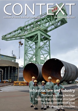
Conserving Ruchill Hospital water tower
The requirement to restore the severely decayed, Category A listed, hilltop Victorian water tower at the former Ruchill hospital, Glasgow, set a challenge to its structural engineers.

[Image: A panoramic view of the tower and its site from the west, before restoration.]
In 2009 WYG was invited by Colliers International (agent for Scottish Enterprise) to assess the remaining dozen buildings at the closed Ruchill Hospital in Glasgow. All were listed and in very bad condition. Sadly, all but one were razed to the ground in 2013. The building that was spared this fate was the Category A listed, 10-storey Victorian water tower, standing foursquare on the hill top at the centre of the site. A condition of demolition of the other buildings was that the tower would be restored to its original condition.
It was important to establish how the diminishing upper parts of the tower had been assembled and what materials had been used. Outwardly it was clear that the tower was primarily a gravity masonry structure, resisting wind loading and supporting four large water tanks on the middle floors. By around 1900 structural steel was available, so the eighth- and ninth-floor structures incorporated grillages of four pairs of RSJ sections, arranged two-above-two to support the inset tower wall masonry – as the tower reduces in plan size through these floors, before terminating in a copper-clad timber cupola. The cupola is restrained to the ninth floor by four vertical iron tension rods.
The design and specification for stabilising and repairing the tower structure were prepared in 2011 with only the knowledge gained in 2009 from visual inspection and study of the original construction drawing of 1898. Intrusive investigation, which could only take place after the contractor had been appointed in late 2012, revealed several serious hidden defects and some significant variations from the 1898 design.
At ninth floor level, the bearings of the two upper pairs of RSJs were found to be much more badly corroded than those for the two lower pairs, because the builder had left the ends exposed to the weather. The same two pairs of RSJs were found to be of considerably smaller section size than the 1898 drawing specified.
At eighth-floor level, severe cracking was found in the south-west corner masonry. This was caused by corrosion where the ends of one of the upper pairs of RSJ sections, also found to have been left exposed. Although the amount of corrosion on the top flange was sufficient to have jacked up the masonry, causing the severe cracking, the loss of section was fortunately insignificant to the RSJs’ integrity.
At fourth- to seventh-floor levels, severe corrosion of the top flanges of the closely-spaced, small-section secondary RSJs was found when the water tanks were removed. This was probably caused by condensation occurring where the cast iron of the tanks had been in contact with the secondary RSJs. The four larger primary RSJs were (perhaps surprisingly) found to be in good condition, even where their bearings had been revealed by trial opening-up in the masonry.
These matters led to considerable modification of our design. In addition to strengthening the eighth-floor steelwork and stabilising the main cupola after finding that the vertical tension restraint rods had corroded away due to years of standing in trapped water, the revised structural works for the restoration now also included:
- Providing new conventional timber flooring where water tanks had been removed from the fourth- to seventh-floor levels, the new joists being fitted between the corroded secondary RSJs, which therefore became redundant but were retained for historical reasons;
- Introducing new steelwork to repair and strengthen the ninth floor, and
- Stabilising masonry which had been weakened by extensive cracking and movement.
Three aspects of the modified design will be described here.
Strengthening the existing lower pairs of RSJs (clear span 4.6 metres), which were now required to carry the undersized upper pairs of RSJs and so would become overloaded, was originally to be executed by site-welding new steelwork beneath the upper pairs of RSJs to convert them into a pair of trusses, such that the new truss members would fit around the cupola restraint steelwork designed in 2009. Welding is not a particularly reversible operation, but there appeared to be no other practical way to make the connections. When the existing steel was tested to check its suitability for welding, contaminant levels and added-element content, especially carbon, were found to be very low. Knowing that wrought iron was sometimes substituted for steel in late-Victorian buildings, it seemed likely that the metal was wrought iron and not steel. Delamination is characteristic of rolled wrought iron of that era, so an alternative to welding had to be found.
An innovative scheme based on plates with friction-bolt connections fitted in the slot between the RSJs in both beam pairs was devised. The fact that the masonry at the ends of the pairs of RSJs had been removed during the intrusive inspection meant that the openings so formed could be used to feed shaped steel plates, each containing a line of tension control bolts (TCBs) into the space between the bottom flanges of the pair of RSJs, then slid into to position from outside the tower. TCBs were used because they can be tightened from one side only, in this case from below the soffit of the beam pair, once the plates had been adjusted to their required positions. Further plates, packers and TCBs were added to the outer flange toes of the RSJs to complete the connections.
The existing bearings for the lower RSJs, which had minimal corrosion damage, were exposed for cleaning, and a coating applied to prevent future contact with any masonry-borne moisture. Other than cleaning and coating then weatherproofing, no attempt to repair the severely corroded bearings for the upper RSJs was necessary as the capacity of the upper RSJ bearings was not required.
The design of the eighth-floor strengthening had been based on the findings from assessment of the existing two pairs of RSJs in each direction, one above the other as for the ninth floor but of greater (6.5m clear) span. The pattern of the cracking in the masonry arching over the eighth-floor window heads suggested that the steelwork was overstressed in bending; calculation confirmed that the overload was significant. It was deduced that the steelwork had been acting in tension, resisting the compressive arch forces. This redistribution of forces relieved the steelwork of some of its bending, explaining why the structure had remained stable over the years.
The structure was strengthened by adding a new steelwork grillage beneath the existing pairs of RSJs. The new steelwork was positioned on new concrete pad-stone bearings in the substantial ashlar-faced piers in the tower walls. An assumption that the piers were constructed from Locharbriggs sandstone was substantiated by petrographic examination. The design work included determination of a pre-load to be jacked into the system so that the joints, splices and bearings would be properly seated. Around half the estimated deadweight of the tower above eighth-floor level was used as the jacking load. Repairs to the cracking were carried out after the jacking operation. Apart from the pad-stone bearings, the completed work is reversible. To mitigate the non-reversible nature of the pad-stones, the contractor made a very good job of fitting the masonry back around the new steelwork.
In the main area of cracking, which was on all four sides between the eighth-floor window heads and ninth-floor level, a girdle was created by installing pairs of horizontal Cintec anchors to tie the cracked masonry together. The inner lines of anchors were sited so that they would occur just below the bearings of the existing lower RSJ pairs at ninth-floor level, so that any tendency for the masonry to fracture vertically due to increased bearing loads from the lower RSJs (which now carry the upper RSJs) would also be resisted.
The design promoted robustness where possible consistent with conserving the historic fabric. Throughout the project the objectives of minimum intervention and reversibility were exercised as far as was reasonably practical.
This article originally appeared in IHBC's Context 146, published in September 2016. It was written by Ian Andrew, a conservation-accredited engineer with WYG.
--Institute of Historic Building Conservation
[edit] Find out more
[edit] Related articles on Designing Buildings Wiki
IHBC NewsBlog
IHBC sponsors Gardens Trust event 23-4 Sept 2026
.jpeg)
'Learning from the Past, Shaping the Future’ takes place in Milton Keynes
Renovations to Frank Lloyd Wright's Fallingwater complete
.jpg)
World Heritage Preserved project opens house for tours again
Shakespeare Birthplace Trust places Hall's Croft on HAR Register
Stratford-upon-Avon home of Shakespeare's daughter is 'At Risk'
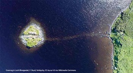
Lady Grange’s House repaired on St Kilda
.jpg)
National Trust for Scotland repairs stone cleit with link to famous island resident
Griff Rhys Jones on BBC Radio 4 Today programme
,_Green_Lane,_Derby.jpg)
The Victorian Society’s President unveiled its latest Top Ten Endangered Buildings 2026.
Need a MATE? Book your place now.

IHBC offers free webinars on applying for IHBC accreditation (Full & Associate).
UK Stained Glass Repository finds windows new homes
How are stained glass windows are rescued, stored and repurposed?
APPGEBE report sets high aims for quality
'Government must not sacrifice quality in drive to build 1.5m homes'
New measures protect Historic Shipwrecks from heritage crime

Underwater cultural heritage benefits from new HE guidance
How could the City of London skyline look in 6 years' time?

Visualisation shows approved planning applications as completed buildings
National Trust for Scotland calls for VAT cuts
Heritage neglect is encouraged by current policies
IHBC's 'Context' Issue 186 features Industrial Heritage
IHBC's members' journal reports on the challenges of conserving infrastructure
Book now for IHBC Annual School 2026
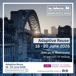
IHBC Annual School is taking place 18-20 June 2026 in Newcastle
RICHeS Research Infrastructure offers ‘Full Access Fund Call’
RICHeS offers a ‘Help’ webinar on 11 March
Latest IHBC Issue of Context features Roofing
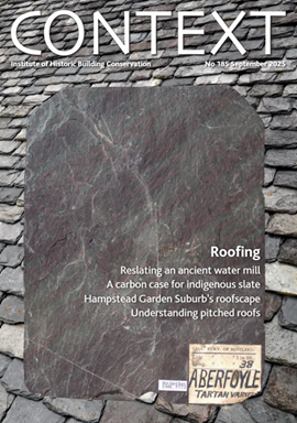
Articles range from slate to pitched roofs, and carbon impact to solar generation to roofscapes
Three reasons not to demolish Edinburgh’s Argyle House

Should 'Edinburgh's ugliest building' be saved?
IHBC’s 2025 Parliamentary Briefing...from Crafts in Crisis to Rubbish Retrofit
IHBC launches research-led ‘5 Commitments to Help Heritage Skills in Conservation’
How RDSAP 10.2 impacts EPC assessments in traditional buildings

Energy performance certificates (EPCs) tell us how energy efficient our buildings are, but the way these certificates are generated has changed.