


Thermography for traditional buildings
A non-destructive method of assessing thermal performance, thermography can be especially valuable when improving energy performance while protecting a building’s historic fabric.
Thermography is a visual method of illustrating invisible heat energy. This is typically captured using an infrared camera, which displays a map of the temperature variations emitted by all objects with a surface temperature above absolute zero (-273°C). Objects are illustrated as thermal patterns, using different colours or shades of grey, depending on the palette selected. The thermal patterns illustrate the variations of heat energy being emitted from the surface of the object.
The subsequent interpretation of the thermal patterns requires an understanding of the environmental conditions at the time of capturing the image, and of the surface characteristics of the materials being viewed. Emissivity (an object’s ability to emit infrared radiation) and reflectivity (the property of reflecting radiation) are the two characteristics of materials which determine how reliable the thermal pattern is in the image. Materials with high emissivity have a low reflectivity and vice versa. Only materials with a high emissivity provide a reliable reading. This is because materials with a low emissivity have a tendency to reflect the temperature of surrounding objects.
Typically, materials such as bricks and plaster have a high emissivity, while metals and glass have a low emissivity. Given that the fabric of many older buildings will be made up from predominantly high emissivity materials, thermography can be a really useful tool for assessing the fabric of new and existing buildings, in particular retrofitted energy-efficiency interventions. The main advantage of using thermography is that you can see what is going on under the skin of a building without having to take the building apart. Having the ability to see invisible heat energy provides valuable data for assessing thermal performance.
Quantitative thermographic assessments of heat loss require precise climatic conditions, which rarely occur, particularly in external environments. As a result, typically only qualitative thermographic building surveys provide robust and reliable data.
Qualitative thermographic building surveys can provide many useful insights, such as the effectiveness of insulation as a barrier to heat loss; occurrences of thermal bridging; sources of air leakage; moisture and damp; and hidden components, such as pipes and wall ties.
There is a clear benefit to using non-destructive infrared thermography in traditional buildings. For example, intrusive investigations – drilling holes or dismantling construction elements – would otherwise be required to identify missing insulation and the location of thermal bridges. Furthermore, it can be difficult to identify the location of air leakage using air-pressurisation tests alone. And moisture and damp often goes unnoticed until it appears on the surface.
Being able to achieve robust and reliable results from qualitative thermography requires professional training and certain environmental conditions at the time of the survey. Being able to use an infrared camera and accompanying software, and understanding and interpreting thermal images, also requires a suitable level of knowledge and experience about the survey process and the building being assessed.
The correct survey process includes ensuring that the current environmental conditions are suitable, as this will maximise the accuracy of the data being collected. Although camera technology has improved over the years, along with the process itself, results still depend on the type of building fabric being surveyed. Knowledge and experience about building materials and construction methods are essential prerequisites for a successful survey.
The criteria for the environmental conditions also vary, depending on whether an internal or external thermographic survey is required. The latter is more challenging. For example, external surveys require no solar radiation on the surface before and during the survey; no precipitation before and during the survey; a temperature difference between the inside and outside the building of at least 5°C, more commonly 10°; and wind speeds of no more than 10 metres per second (m/s), or preferably 6 m/s are recommended. The length of time with no solar radiation and precipitation prior to undertaking a survey depend on the absorptance (the effectiveness of absorbing heat energy) of the building material.
To overcome the need to avoid solar radiation, many experts currently recommend undertaking thermographic surveys in the dark. Others suggest that a cold, overcast day is sufficient. It is also often advocated that thermographic surveys should be undertaken only in the winter, which could be a significant limitation to their use. Previous work has achieved reliable results to identify thermal bridging using thermography during the early hours of the morning during the summer. The most important consideration is taking due account of the environmental conditions during interpretation.
Internal surveys have fewer restrictions. With the exception of temperature, most of the criteria used for external climatic conditions do not apply. However, the temperature difference between the inside and outside of the building is critical for both internal and external thermographic surveys. Subject to the restrictions imposed by the resolution of the infrared camera, the greater the temperature difference, the better the detail that is visible in the thermal image.
Camera quality and resolution are critical for undertaking thermographic surveys of building fabric, particularly when needing to capture a whole facade. Sometimes it is also necessary to use a wide-angle lens. Occasionally images have to be stitched together, depending on the size of the building. The cost of cameras rises significantly in line with increases of the resolution, and with the addition of any accessories, but there is no substitute for having the right equipment for the job.
One great advantage of using thermography during retrofit is for communicating what has been done. Capturing the whole facade before and after insulating is a great way of visually highlighting the improvements that have been made. More detailed and close-up images are also useful for identifying any gaps and subsequent thermal bridging.
When interpreting thermal images taken inside the building, colours representing cold areas are an indication of heat loss. These areas of heat loss can be either expected as part of the design, or unexpected and indicating a potential problem. Issues could include inappropriate installation, poor workmanship or other unforeseen consequences.
To demonstrate the use of thermography as part of a retrofit project, the following example illustrates a traditional solid-walled house after receiving retrofitted external wall insulation (EWI). The independent survey was undertaken as part of the monitoring element of the energy efficiency improvement programme.
The house, built pre-1919, is of traditional construction. The design of the EWI installation was undertaken by the system supplier and commissioned by the principal contractor. While the overall aesthetics of the house appeared to have been improved, primarily due to the whole-street approach taken, a closer look under the surface and at critical junctions tells a slightly different story.

|

|
| An internal photograph of an external wall (Images: Jo Atkinson). | An internal thermal image of that external wall. |
The images shown here are a corresponding thermal image and photograph of the internal surface of an external wall after the EWI had been installed. The blue colour of the wall in the thermal image indicates that the surface is colder than the surrounding surfaces and the ambient air temperature. From the naked eye and the photograph it was not possible to identify this anomaly. However, an external thermal image and a discussion with the home owner did suggest a possible cause. The thermal image of which a detail is shown on the front cover of this issue of Context illustrates the external facade of the dwelling. The thermal image appears to confirm the resident’s claim that water was pooling on the first floor window sill, and was travelling down behind and penetrating the EWI.
This article originally appeared in IHBC's Context 149, published in May 2017. It was written by Jo Atkinson, an architectural technologist and qualified thermographer, who leads the Carbon Trust’s housing-related work.
--Institute of Historic Building Conservation
[edit] Related articles on Designing Buildings Wiki
- Assessing moisture in porous building materials.
- Bonfield Review.
- BREEAM Testing and inspecting building fabric.
- Building survey.
- Ecobuild 2016 - Making the business case for large scale retrofit investment.
- Energy efficiency of traditional buildings.
- Energy-related retrofits of buildings and urban areas, a comparison between Germany and the UK.
- Home Energy Masterplan.
- How to deal with retrofit risks.
- IHBC articles.
- National Refurbishment Centre.
- New energy retrofit concept: 'renovation trains' for mass housing.
- Renovation v refurbishment v retrofit.
- Retrofit coordinator.
- Retrofit, refurbishment and the growth of connected HVAC technology.
- Retrofit.
- Retrofitting traditional buildings.
- The Each Home Counts report and traditional buildings.
- The Institute of Historic Building Conservation.
- Thermal imaging of the building fabric in the net zero world.
- Thermal imaging to improve energy efficiency in building design.
- Thermography.
- Traditional buildings health check - pilot project review.
- Understanding dampness.
- Understanding the performance of solid walls.
IHBC NewsBlog
IHBC sponsors Gardens Trust event 23-4 Sept 2026
.jpeg)
'Learning from the Past, Shaping the Future’ takes place in Milton Keynes
Renovations to Frank Lloyd Wright's Fallingwater complete
.jpg)
World Heritage Preserved project opens house for tours again
Shakespeare Birthplace Trust places Hall's Croft on HAR Register
Stratford-upon-Avon home of Shakespeare's daughter is 'At Risk'
Lady Grange’s House repaired on St Kilda
.jpg)
National Trust for Scotland repairs stone cleit with link to famous island resident
Griff Rhys Jones on BBC Radio 4 Today programme
,_Green_Lane,_Derby.jpg)
The Victorian Society’s President unveiled its latest Top Ten Endangered Buildings 2026.
Need a MATE? Book your place now.

IHBC offers free webinars on applying for IHBC accreditation (Full & Associate).
UK Stained Glass Repository finds windows new homes
How are stained glass windows are rescued, stored and repurposed?
APPGEBE report sets high aims for quality
'Government must not sacrifice quality in drive to build 1.5m homes'
New measures protect Historic Shipwrecks from heritage crime

Underwater cultural heritage benefits from new HE guidance
How could the City of London skyline look in 6 years' time?

Visualisation shows approved planning applications as completed buildings
National Trust for Scotland calls for VAT cuts
Heritage neglect is encouraged by current policies
IHBC's 'Context' Issue 186 features Industrial Heritage

IHBC's members' journal reports on the challenges of conserving infrastructure
Book now for IHBC Annual School 2026

IHBC Annual School is taking place 18-20 June 2026 in Newcastle
RICHeS Research Infrastructure offers ‘Full Access Fund Call’
RICHeS offers a ‘Help’ webinar on 11 March
Latest IHBC Issue of Context features Roofing
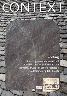
Articles range from slate to pitched roofs, and carbon impact to solar generation to roofscapes
Three reasons not to demolish Edinburgh’s Argyle House

Should 'Edinburgh's ugliest building' be saved?
IHBC’s 2025 Parliamentary Briefing...from Crafts in Crisis to Rubbish Retrofit
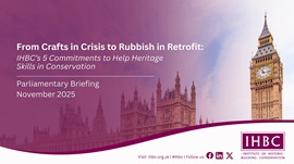
IHBC launches research-led ‘5 Commitments to Help Heritage Skills in Conservation’
How RDSAP 10.2 impacts EPC assessments in traditional buildings

Energy performance certificates (EPCs) tell us how energy efficient our buildings are, but the way these certificates are generated has changed.