


Detail drawing

Detail drawings provide a detailed description of the geometric form of a part of an object such as a building, bridge, tunnel, machine, plant, and so on. They tend to be large-scale drawings that show in detail parts that may be included in less detail on general arrangement drawings.
Detail drawings may be used to demonstrate compliance with regulations and other requirements, to provide information about assembly and the junctions between components, to show construction details, detailed form, and so on, that would not be possible to include on more general drawings.
They may include dimensions, tolerances, notation, symbols and specification information, but this should not duplicate information included in separate specifications as this can become contradictory and may cause confusion.
They may consist of two-dimensional orthogonal projections showing plans, sections and elevations and may be drawn to scale by hand, or prepared using Computer Aided Design (CAD) software. However, increasingly, building information modelling (BIM) is being used to create detailed three-dimensional representations of buildings and their components.
Detail drawings may be confused with ‘detailed design drawings’ which might describe the drawings produced during the detailed design stage, (sometimes referred to as 'developed design' or 'definition'). Detailed design is the process developing the design so that it is dimensionally correct and co-ordinated, describing all the main components of the building and how they fit together. Not all drawings produced during this stage will necessarily be detail drawings.
They are also distinct from the definition of ‘working drawings’ which provide dimensioned, graphical information that can be used by a contractor to construct the works, by suppliers to fabricate components of the works or to assemble or install components. Again, not all working drawings will necessarily be detail drawings.
[edit] Related articles on Designing Buildings
- As-built drawings and record drawings.
- Assembly drawing.
- Building information modelling.
- Component drawing.
- Computer aided design.
- Concept drawing.
- Demystifying design processes of architectural details.
- Design drawings.
- Electrical drawing.
- Engineering drawing.
- Exploded view.
- General arrangement drawing.
- Geometric form.
- Installation drawings.
- North American Paper Sizes
- Notation and symbols.
- Packaging.
- Paper sizes.
- Production information.
- Projections.
- Residential design and 3D rendering.
- Scale drawing.
- Section drawing.
- Shop drawings.
- Specification.
- Technical drawing.
- Technical drawing pen sizes
- Working drawings.
Featured articles and news
Costs and insolvencies mount for SMEs, despite growth

Construction sector under insolvency and wage bill pressure in part linked to National Insurance, says report.
The place for vitrified clay pipes in modern infrastructure

Why vitrified clay pipes are reclaiming their role in built projects.

Research by construction PR consultancy LMC published.
Roles and responsibilities of domestic clients
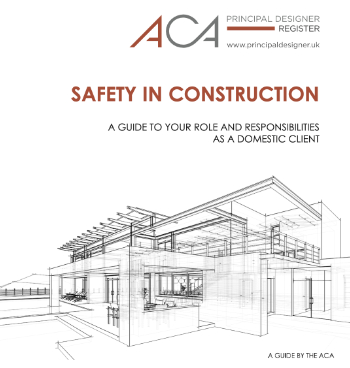
ACA Safety in Construction guide for domestic clients.
Fire door compliance in UK commercial buildings
![]()
Architect and manufacturer gives their low down.
Plumbing and heating for sustainability in new properties
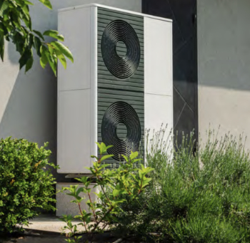
Technical Engineer runs through changes in regulations, innovations in materials, and product systems.
Awareness of the Carbon Border Adjustment Mechanism
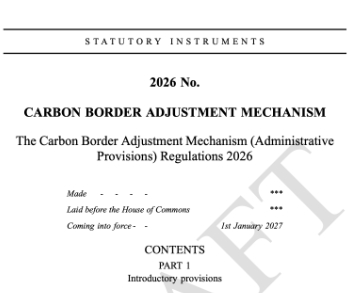
What CBAM is and what to do about it.
The new towns and strategic environmental assessments
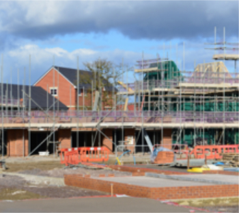
12 locations of the New Towns Taskforce reduced to 7 within the new towns draft programme and open consultation.
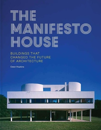
Buildings that changed the future of architecture. Book review.
The Sustainability Pathfinder© Handbook
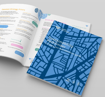
Built environment agency launches free Pathfinder© tool to help businesses progress sustainability strategies.

Government outcome to the late payment consultation, ECA reacts.
IHBC 2025 Gus Astley Student Award winners
![]()
Work on the role of hewing in UK historic conservation a win for Jack Parker of Oxford Brookes University.
Future Homes Building Standards and plug-in solar
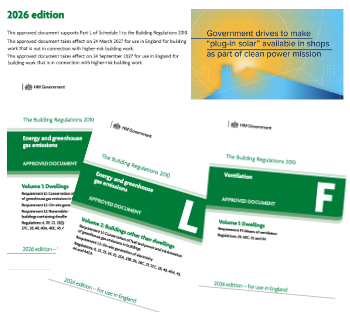
Parts F and L amendments, the availability of solar panels and industry responses.
How later living housing can help solve the housing crisis

Unlocking homes, unlocking lives.
Preparing safety case reports for HRBs under the BSA
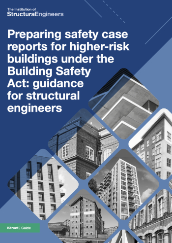
A new practical guide to preparing structural inputs for safety cases and safety case reports published by IStructE.
Male construction workers and prostate cancer

CIOB and Prostate Cancer UK encourage awareness of prostate cancer risks, and what to do about it.
Comments
what kinds of scales we r using for detail drawings ? metric & architectural
Thank you :)