


Scale drawing

|

|
Contents |
[edit] What are scale drawings?
Scale drawings are drawings that represent something at a size other than their full size. They can represent things at either a larger or a smaller scale than full size, depending on the size of the thing they are representing and the use to which the drawing will be put. The scale describes the ratio between a distance at full size, and the distance at the scale used that would be the same length.
[edit] What are scale drawings used for?
Scale drawings are used to illustrate items that it is not useful or convenient to draw at their actual size. This may be because drawing the item at full size would be unmanageable, or would not easily fit on a single sheet of paper (such as a building), or alternatively because items need to be drawn larger than full size to adequately represent all the detail that needs to be communicated (such as a complex connection).
The scale of drawings is described as a ratio using the notation:
| A distance at full size : The distance at the scale used that would be the same length. |
For example:
- A full size drawing would be 1:1 (or sometimes 1/1 or ‘one to one’).
- A half size drawing would be 1:2.
- A tenth size drawing would be 1:10.
- A double size drawing would be 2:1.
[edit] What are the most commonly used scales for drawings?
In the construction industry a range of scales are generally used depending on the nature of the drawing. For example:
- A location plan at 1:1000.
- A site plan at 1:200.
- A floor plan at 1:100.
- A room plan at 1:50.
- A component drawing at 1:5.
- An assembly drawing at 1:2.
[edit] How should scales be used on drawings?
It is important that the scale used is noted on the drawing. In addition, because of the ease of reproducing, printing and re-sizing drawings, it is important to note the original sheet size that the scale was drawn at, so for example A4, A3, A2, A1, A0, and so on.
See Paper sizes and Technical drawing pen sizes for more information.
Where a single sheet includes a range of drawings with different scales, these should all be noted.
In some cases, it may be appropriate to use more than one scale on a single drawing, for example, to show the elevation of land across across a significant distance. In this case, differences in elevation might be illustrated at a larger scale and a smaller scale used for horizontal distances. Here, the scale might be noted on the axes of the drawing, or actual distances shown on the axes.
In other cases a scale might use more than one unit of measurement. For example, the length of an arrow on an air flow diagram might represent the velocity of the air, e.g. 1 cm = 0.1 m/s.
The use of computer aided drawing (CAD) and building information modelling (BIM) has introduced a new concept to this process, as in this case, digital models are effectively created at full size. Drawings of any scale can then be generated from the model.
[edit] Related articles on Designing Buildings
- As-built drawings and record drawings.
- Assembly drawing.
- Blueprint.
- Building information modelling.
- Component drawing.
- Computer aided design.
- Concept drawing.
- Design drawings.
- Detail drawing.
- Drawing board.
- Elevations.
- Engineering drawing.
- General arrangement drawing.
- Installation drawings.
- Manual drafting techniques.
- North American Paper Sizes
- Notation and symbols.
- Paper sizes (ISO 216 A, B and C series).
- Perspective.
- Projections.
- Scale.
- Scale rule.
- Schematic.
- Section drawing.
- Shop drawings.
- Site plan.
- Symbols on architectural drawings.
- Technical drawing.
- Technical drawing pen sizes.
- Techniques for drawing buildings.
- Types of drawing.
- Working drawing.
Featured articles
Check out some of the best features and news from Designing Buildings as well as key stories from around the web.
![]()
New and updated CLC building safety guidance.
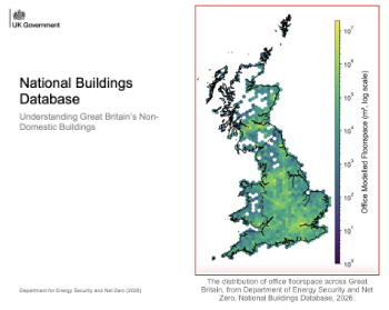
New UK National Buildings Database.
Building Safety Wiki Interviews

Chief executive of the British Woodworking Federation.
Planning condition discharge in England and Wales

A brief explanation from a building compliance expert, with further links.
Overheating guidance and tools for building designers

Guidance for dealing with element of building fabric control that have increasing importance.
Shading for housing, a design guide

From the Good Homes Alliance and British Blind and Shutter Association.
UK Standard Skills Classification (SSC)

A shared framework for describing skills needs.
Social media ban consultation comes to close

CIOB urges UK Government to consider social media’s role in careers guidance in ban debate.
The latest of eight Skills England apprenticeship units

The addition of battery manufacturing welcomed by ECA with a warning about the risks of fast-tracked apprenticeship units.
Building Control Independent Panel final report
A precis of a key report led by Dame Hackitt with full recommendations and link to the government response.
Building Safety recap April, 2026
A short and longer run-through of the month, with links to further information and sources.