




Installation drawings

Installation drawings are developed from co-ordinated detail drawings and present the information needed by trades to install part of the works. This may be particularly important for complex installations such as plant rooms, data centres, ventilation systems, underfloor heating, and so on.
They may be prepared by the consultant team, or may be prepared by contractors, sub-contractors or suppliers and submitted for approval.
They may comprise plans, sections and elevations, but increasingly building information modelling (BIM) is being used to create detailed 3 dimensional representations of buildings and their components which may include installation information.
Installation drawings may include information about:
- Precise positioning.
- Supports and fixings.
- Information from manufacturers shop drawings.
- Space allowances for installation.
- Builders work in connection, such as; cutting and sealing holes, chasing block and brickwork for conduits or pipes, lifting and replacing floors, constructing plinths and so on.
- Plant or equipment requirements.
- Requirements for service connections.
- Requirement to leave access space for operation and maintenance.
- Other maintenance access requirements such as access panels, decking, platforms, ladders and handrails.
It is important that the information presented is carefully co-ordinated so that clashes are avoided.
Installation drawings may include specification information, or this may be provided in a separate specification, but information should not be duplicated as this can become contradictory and may cause confusion.
Design Framework for Building Services 5th Edition (BG 6/2018), written by David Churcher, John Sands & Martin Ronceray, and published by BSRIA in June 2018 suggests that installation drawings are:
|
Drawings based on the Technical Design drawings or coordinated working drawings with the primary purpose of defining that information needed by the tradesmen on site to install the works. The main features of installation drawings should be as per coordinated working drawings, plus:
|
[edit] Related articles on Designing Buildings Wiki
- As-built drawings and record drawings.
- Assembly drawing.
- Concept drawing.
- Design drawings.
- Detail drawing.
- Elevations.
- Engineering drawing.
- General arrangement drawing.
- Projections.
- Scale drawing.
- Section drawing.
- Shop drawing.
- Technical drawing.
- Types of drawing.
- Working drawing.
- Component drawings
Featured articles
Check out some of the best features and news from Designing Buildings as well as key stories from around the web.

CIOB celebrates positive Ofsted report.

The Building Safety Regulator announces a call for evidence.

Government approach could undermine delivery and regeneration.
World's first mass timber data centre.
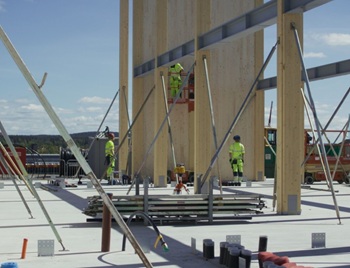
The overlooked environmental aspect of data centre development.
Introduction to radon awareness

New technical information sheet published by CIOB.

Updated supplier guide can help electrical contractors engage with NHP.

CIAT confirm the winners of the 2026 architectural technology awards.

Government launches a one stop shop for flood preparedness.

Sir Edwin Lutyens: Britain's greatest architect? Book review.

CIOB publishes free template to help assess and manage risks.
ECA's reflections on Party Conference season

Burnham wants to be confident of winning before asking for a fresh mandate.
New Chief Construction and Scientific Adviser

Sergio Cavalaro, Professor of Infrastructure Systems at Loughborough University.