


Technical drawing
The term ‘technical drawing’ has a very broad meaning, referring to any drawing that conveys the way that something functions or how it is constructed. Technical drawings are intended to convey one specific meaning, as opposed to artistic drawings which are expressive and may be interpreted in a number of ways.
Most drawings prepared during the design and construction of buildings might be considered to be technical drawings.
Technical drawings will generally become more complete, more specific and will increase in detail as a project progresses. They may include:
- Sketches.
- Design intent drawings.
- Detail drawings.
- Working drawings.
- General arrangement drawings.
- Assembly drawings.
- Component drawings.
- Shop drawings.
- Installation drawings.
- As-built drawings and record drawings.
Technical drawings may comprise two-dimensional (orthogonal) plans, sections and elevations, or may include three-dimensional or exploded projections. They may be drawn to scale by hand, or prepared using Computer Aided Design (CAD) software. However, increasingly, building information modelling (BIM) software is being used to create three-dimensional representations of buildings and their components. BIM models may be described as 'design intent models' during the early stages of development but then may evolve into 'virtual construction models' (VCM) and finally 'as-constructed models'.
It is important that the purpose for which technical drawings are being prepared and the people that will use them are carefully considered to ensure they are properly structured and adopt an appropriate presentational techniques.
The scale at which drawings are prepared should reflect the level of detail of the information they are required to convey, and graphical techniques such as the use of different line thicknesses and hatching can help provide greater clarity.
To help convey the precise meaning of information, technical drawings may include title blocks, dimensions, notation and symbols. To ensure their meaning is concise and unambiguous, it is important that these are consistent with industry standards.
Specification information may be included on technical drawings or in a separate specification, but information should not be duplicated as this can become contradictory and may cause confusion.
The broad term ‘technical drawing’ should not be confused with the specific meaning of drawings prepared during the technical design stage. These are drawings prepared after the detailed design (or 'developed design' or 'definition') has been completed, but before the construction contract is tendered or construction begins. These drawings will often be prepared by specialist subcontractors.
[edit] Related articles on Designing Buildings
- As-built drawings and record drawings.
- Assembly drawing.
- Common mistakes on building drawings.
- Component drawings.
- Concept drawing.
- Design drawings.
- Detail drawing.
- Drawing board.
- Elevations
- Engineering drawing.
- General arrangement drawing.
- Installation drawings
- North American Paper Sizes.
- Notation and symbols.
- Paper sizes.
- Projections.
- Scale drawing.
- Scale rule.
- Section drawing.
- Shop drawing.
- Technical design.
- Technical drawing pen sizes.
- Types of drawing.
- Working drawing.
Featured articles
Check out some of the best features and news from Designing Buildings as well as key stories from around the web.

UKCW Birmingham returns with bold new theme and focus.
New guidance published on competence requirements for self-certification schemes.
Construction Management, 8 July

NEETs crisis drives interest in trades, but apprenticeships barriers remain.
Passive fire protection webinar

MEP services penetration seals.

Where its at podcast (and video) - The role of the Architectural Technologist as an Expert Witness.
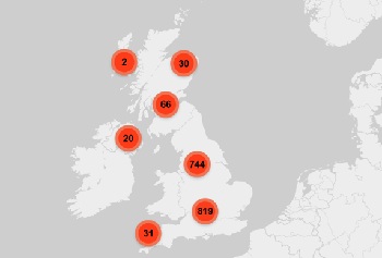
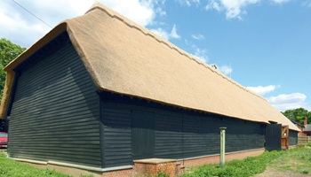
More than 200 remarkable buildings added to SAVE’s Buildings at Risk register.

Government scraps pre-application consultation for Nationally Significant Infrastructure Projects.
Historic England and infrastructure
New projects offer opportunities for the historic environment and local communities.
Construction Management, 2 July

Construction deaths halve in two years.
Green Book changes to drive investment in all parts of UK.
Minimum energy efficiency standards (MEES)
![]()
CIAT briefing on response to consultations for privately rented non-domestic properties.
Comments
This would all be so much more useful if we could actually see examples of all the different types of drawings.