


Cavity tray

The external masonry walls of modern buildings are generally cavity walls, that is, they are formed by an inner leaf and an outer leaf of masonry, tied together, but separated by an air gap or ‘cavity’.
The cavity prevents moisture transmitting from the outer leaf to the inner leaf. It can also provide a ventilation space, allowing moisture within the wall construction to vent to the outside, and can provide a space for the installation of cavity wall insulation.
It is only since the 1920s that external masonry walls in the UK have widely adopted a cavity construction. Before this, they were generally a solid construction.
Cavity trays are included in cavity wall constructions where there are penetrations across the cavity, such as:
- At an abutment with a roof.
- Above openings such as doors and windows.
- Where extensions are constructed against existing walls.
- Above concrete slabs or beams.
- Above airbricks, ducts and pipes.
- At the bottom of a wall, if the cavity does not extend 225 mm below the damp-proof course.
Cavity trays prevent moisture being carried to the inner leaf. Very broadly, cavity trays tend to prevent moisture that is travelling downwards from being carried to the inner leaf, whereas damp-proof courses tend to be used to prevent rising damp.
Approved document C of the Building Regulations, Site preparation and resistance to contaminants and moisture, suggests that a cavity tray (or damp-proof course or closer) should be provided to ensure water drains outwards:
- Where the downward flow will be interrupted by an obstruction such as a lintel.
- Under openings, unless there is a sill and the sill and its joints will form a complete barrier.
- At abutments between walls and roofs.
 [Image source: Approved document C, Site preparation and resistance to contaminants and moisture]
Cavity trays can be formed using a pliable material such as lead, but more commonly they are pre-formed, with a wide range of shapes allowing for different cavity widths, corners, stop ends, steps, lintel shapes, arch shapes and sometimes incorporating external flashing.
Cavity trays must always be bedded onto fresh mortar.
Weep holes must be provided in the external leaf of the wall to allow moisture to drain to the outside. Weep holes are generally created by omitting mortar from the vertical joint between bricks, typically at 450-900 mm centres. They may include plastic weep vents which incorporate a baffle structure to prevent rain from penetrating through the hole and preventing insects from entering the cavity and provide a drip at the front lip to aid drainage.
Care must be taken where there is insulation in the cavity to ensure that both the insulation and the cavity tray continue to function correctly. This can be particularly problematic where blown insulation is retrofitted in to existing cavities.
Where it is necessary to insert cavity trays into existing walls, for example, if an extension is being built against an existing wall, this can be done by removing brickwork a section at a time, or by inserting self-supporting cavity trays through slots cut in the wall.
Standards for cavity trays are described in BS 5628 Code of practice for the use of masonry and BS 8215 Code of practice for design and installation of damp-proof courses in masonry construction.
[edit] Related articles on Designing Buildings
- Building damp-free cavity walls.
- Cavity wall.
- Cavity wall insulation.
- Cold bridge
- Condensation.
- Damp.
- Damp-proof course.
- Defects in brickwork
- Defects in stonework.
- Flashing.
- Insulation.
- Interstitial condensation.
- Lintel.
- Parapet.
- Penetrating damp.
- Rising damp.
- The cavity wall real performance question.
- Types of brick bonding.
- Vapour barrier.
- Wall ties.
- Wall tie failure.
- Weep hole.
Featured articles
Check out some of the best features and news from Designing Buildings as well as key stories from around the web.
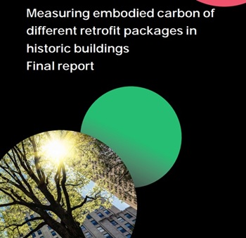
Historic England publishes research into embodied carbon when retrofitting traditional buildings.

New Prime Minister delivers on ECA call for cut in electricity costs.

CIOB reacts to the announcement of Andy Burnham as Prime Minister.

Heritage and conservation science workforce survey - Have your say.

England's Suburbs 1820-2020. Book review.

New, more proportionate and targeted approach for higher-risk building assessments.
Government brings British Steel into public ownership.

UKCW Birmingham returns with bold new theme and focus.
New guidance published on competence requirements for self-certification schemes.
Construction Management, 8 July
NEETs crisis drives interest in trades, but apprenticeships barriers remain.
Passive fire protection webinar

MEP services penetration seals.

Where its at podcast (and video) - The role of the Architectural Technologist as an Expert Witness.