Resonant column method
Contents |
introduction
Background
The resonant column method was initially developed by Japanese engineers: Ishimoto & Iida (1937). It was made popular in the 1960s by authors such as Hall & Richart (1963), Drnevich et al. (1967) and Hardin & Black (1968). The resonant column apparatus has been used to measure the dynamic response of soils including the shear and elastic modulus based on the theory of wave propagation in prismatic rods.
Shear modulus (G)
The resonant column method was conventionally used in torsion to measure the shear modulus (G) of the material. In most cases, the clamped-free configuration has been chosen for research purposes as its mathematical derivation is more straightforward. In the clamped-free test, a cylindrical specimen is fixed at the base and excited via a drive mechanism attached to its free end. The resonant frequency (omega) is measured from which the velocity of the propagating wave is derived. Based on the derived velocity and the sample’s density, the low-strain shear modulus (G) of the material can be computed from the basic equation for torsional vibration.
Young modulus (E)
The resonant column can also be used in flexural excitation to determine the material’s Young modulus (E). The conventional method with long samples allowing the application of Rayleighod’s energy method and Euler-Bernoulli beam theory, disregarded the shear strain energy and rotary inertia effect. When the tested specimen is short in length compared to its diameter, the effects of rotation and shear deformation of the samples during flexure can be substantial. These effects can be significant in interpreting data from flexural test, especially at high frequencies. Therefore, the Euler-Bernoulli theory of flexural vibration of elastic beam is found to be inadequate for short specimens and also for the prediction of higher modes of vibration.
To be more accurate, Timoshenko beam theory is used as a model for this interpretation. The theory was developed by Ukrainian scientist Stephen Timoshenko in the 20th century and takes into account shear deformation and rotary inertia. Different frequency equations for the clamped-free Timoshenko beam with an end mass in flexural vibration are solved to compute the value of elastic stiffness (E).
The resonant column method
Resonant column for torsional excitation
In the standard torsional resonant column (Stokoe cell SBEL D1128) as mentioned in Allen and Stokoe (1982), the specimen is rigidly fixed at the base while torsional oscillation is applied to the free end by a drive head. The basic equations for the clamped-free resonant column subjected to torsion are:
The derivation of these equations is based on the assumption that the rotation is small and each transverse section remains plane and rotates about its centre. All the terms expressed in equation (2.1) are functions of the geometric properties of the specimen, except omega n. Treating the system as a single degree of freedom system, the resonant frequency measured in the resonant column apparatus is the damped natural frequency (omega d) but is sufficiently close to the natural frequency (omega n). In this case, the error can be tolerable as omega d is within 1% of omega n. Solving equation (2.1) and (2.2) with omega n, the shear wave velocity (Vs) can be found from which the shear modulus of the material (G) can be derived by rearranging equation (2.3).
Resonant column for flexural excitation
Finding the Young modulus by Euler-Bernoulli beam theory (short samples)
The RCA can also be used to measure the Young modulus (E) of the material. Cascante et al. (1998) modified the standard Stokoe torsional resonant column (Stokoe cell SBEL D1128) to include flexural vibration mode.
In the original configuration, four pairs of excitation coils were connected in series to produce a net torque at the top of the sample. In Cascante’s modified version, the coils are reconnected so that only two magnets are used to produce a net horizontal force on top of the specimen.
In the reduction of data for flexural excitation, the specimen and its drive head can be idealised as an elastic column with a rigid point mass at the top free end (Fig 3). The behaviour of the system is assumed to be elastic. Cascante et al. (1998) has developed a general mathematical formulation for the angular resonant frequency by using Rayleigh’s energy method and Euler Bernoulli beam theory. Based on this general equation, the Young Modulus (E) can be determined by:
In previous literature, as the cross-sectional dimensions of the sample were small in comparison with its length, Euler-Bernoulli beam theory has been used to treat the boundary conditions and derive the frequency equation, from which E could be determined.
Finding the Young modulus by Timoshenko beam theory (long samples)
When the tested specimens are short in length compared to their thicknesses, the effect of shear deformation during flexure is significant which can result in possible discrepancies in interpreting data from flexural test. On the other hand, the effect of rotation is large when the curvature of the beam is large relative to its thickness. This is true when the beam is short in length compared to its thickness. Therefore, Timoshenko beam theory is used in this interpretation as it takes into consideration the effect of shear deformation and rotary inertia in which the conventional Euler-Bernoulli theory doesn’t. During vibration, a typical element of a beam not only performs translatory movement, but also rotation. With shear deformation being considered, the assumption of the elementary Euler-Bernoulli theory that ‘’plane section remains plane’’ is no longer applicable. Therefore, the angle of rotation which is equal to the slope theta of any section along the length of the beam cannot be obtained by simple differentiation of the transverse displacement y. Thus, it results in two independent motions theta(x,t) and y(x,t).
Timoshenko gave the coupled equations of motion for the beam with constant cross-section as:
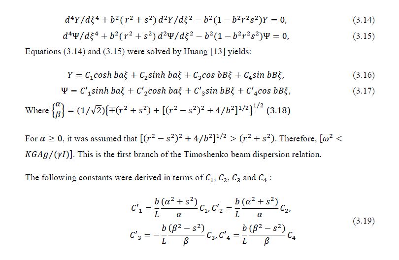
Bruch and Mitchell (1987) investigated a particular case of a cantilevered Timoshenko beam with a tip mass. By applying the boundary conditions and using Huang’s non-dimensional variables, the solutions to the coupled equations are determined as functions of the Young modulus (E), the Shear modulus (G), material’s density (rho), the angular natural frequency (omega n) and the geometry of the specimen. Bruch and Mitchell derived the frequency equation of the beam in flexural excitation by inserting the solutions to the coupled equations (2.6) and (2.7) into the boundary conditions, from which the matrix equation can be determined. By taking the determinant of the coefficient matrix equation, the resonant frequency equation was found from which the Young modulus (E) can be calculated.
Liu (1989) suggested three ways in which the work of Bruch and Mitchell could be further extended:
(i) The base condition for the beam-mass system considered in [3] should be modeled as an imperfect clamped support (or elastic support),
(ii) The tip mass’s centre of gravity is not practically right at the top of the beam but usually at a distance from the beam tip,
(iii) the shear coefficient depends on both the shape of the cross-section and the Poisson ratio. Liu added springs at the hub to simulate the imperfect clamped support therefore the boundary condition also includes the spring’s properties which are the rotational spring constant and translational spring constant. By substituting the general solution into the new boundary conditions, Liu gave the improvement of Bruch and Mitchell’s frequency equation for the mass-loaded clamped-free Timoshenko beam.
The shear coefficient in Timoshenko’s beam theory is a dimensionless quantity, dependent on the shape of the cross section, which accounts for the fact that the shear stress and shear strain are not uniformly distributed over the cross section of the specimen. Cowper (1966) developed a new formula for the shear coefficient from the derivation of the equations of Timoshenko beam theory. For a circular cross-section, the value of K was given in terms of the Poisson ratio as:
Farghaly (1993) offered suggestion to extend Liu’s work by applying Timoshenko beam theory in treating the boundary conditions. He realised that the use of Euler-Bernoulli theory in the boundary conditions could result in inaccurate natural frequencies calculated, particularly for high slenderness ratios and higher modes of vibration. Farghaly’s model also includes the root flexibilities and the tip mass’s eccentricity.
The work of Bruch and Mitchell (1987), Liu (1989) and Farghaly (1993) were in an attempt to simulate the motion of a flexible robot arm modeled as a cantilevered Timoshenko beam with a lumped mass and lumped moment of inertia at the free end. However, for the purpose of this essay, their resonant frequency equations were considered to be adequate for use in computing the material’s Young modulus from the flexural resonant column test, if the angular natural frequency is known.
Using Timoshenko’s beam theory for resonant column testing
Frequency equation by Bruch and Mitchell
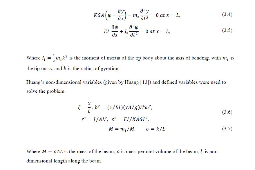
Bruch and Mitchell started with the original coupled equations of motion given by Timoshenko for the beam with constant cross section:
From the simple harmonic motion equations:
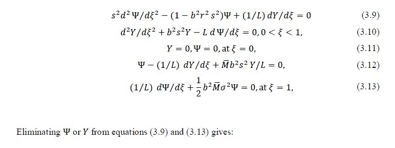
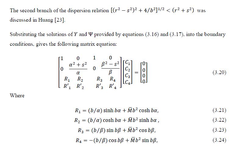
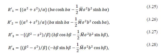
Using the non-dimensional variables and series of equations (3.1) to (3.3), equations (3.4) reduced the problem to:
Taking the determinant of the coefficient matrix equation (3.20) gives the frequency equation, from which the elastic stiffness can be computed with the natural resonant frequency (omega n) as an input.
Frequency equation by Liu
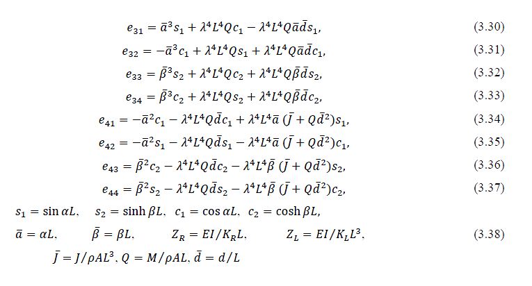
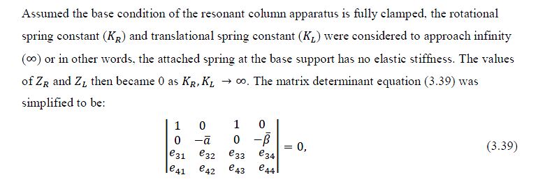
Liu [16] introduced a rotational spring constant (Kr) and a translational spring constant (Kl) to model the imperfection of a clamped support. For simplicity, assuming the base of the resonant column is perfectly clamped, the values of the spring constants (Kr) and (Kl) therefore approach infinity. The distance from the beam tip to the centre of the added mass (d) was added to model the eccentricity. Moment of inertia of the added mass (J) was also included in the revised matrix equation to improve the accuracy of the original model by Bruch and Mitchel. Liu started from the single free vibration equation of a Timoshenko beam given in [16], rather than the coupled equation of motion as in Bruch and Mitchell’s. The frequency equation given by Liu is:
In which
Equation (3.39) was solved using Matlab with the same inputs as in the case of Bruch and Mitchell’s model, plus the eccentricity and moment of inertia of the tip mass, to evaluate the sample’s elastic stiffness.
Frequency equation by Farghaly
Liu has derived a frequency equation to further improve the work of Bruch and Mitchell. The root flexibility, eccentricity and moment of inertia of the tip mass have been taken into consideration to improve the accuracy on modeling a robot arm as a clamped-free Timoshenko beam with a lumped mass and a lumped moment of inertia at its free end. The same idea of simulating a robot arm by Timoshenko beam theory can be used to model the resonant column apparatus when the sample is short in length relative to its diameter. Farghaly commented in his published paper that in [16], Liu used Timoshenko beam theory for the system differential equation, while Euler-Bernoulli theory was applied to treat the boundary conditions. Farghaly stressed that, when using Liu’s formula to compute the resonant frequency with proper inputs, inaccurate natural frequencies maybe obtained, particularly for significant values of the slenderness ratio and higher modes of vibration.
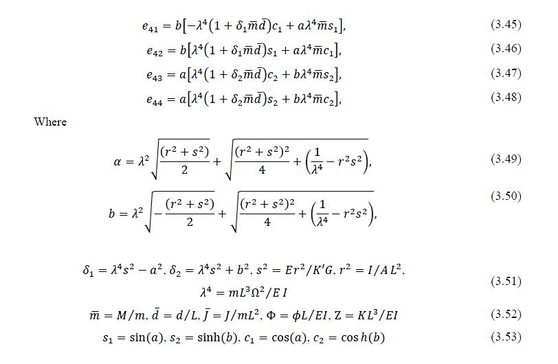
The system frequency equation in terms of the root rigidity parameters can be written as:
In which
In theory, to model the perfectly clamped support condition of the resonant column, the spring constants theta and K should be made to approach infinity. However, in Matlab, for simplicity, extreme values have been assigned to theta and K to give significant values of the root rigidity parameters theta and Z. As mentioned in Farghaly (1992), when using the matrix determinant equation (3.40) to compute the resonant frequencies, inaccurate results might be obtained for large values of the slenderness ratio. According to Liu in Author’s Reply (1992), from his own practical point of view, if one can accept the idea of treating a complicated cantilever structure as a Timoshenko beam, then the discrepancies caused by non-exact boundary conditions might be considered as tolerable.
External references
- Alan, K. (2011). Stiffness and damping of sand at small strain using a resonant column. Civil Engineering 3rd year Individual Project, University of Southampton.
- Allen, J. C. and Stokoe, K. H. (1982). Development of resonant column apparatus with anisotropic loading. Geotechnical Engineering Report GR82-28, Civil Engineering Dept., University of Texas at Austin.
- Banerjee, J. R. (2001). Frequency equation and mode shape formulae for composite Timoshenko beams. Composite Structures 51 , 381-388.
- Bisplinghoff, R. L., and Ashley, H. (1962). Principles of Aeroelasticity. New York: Dover.
- Bruch, J. C., and Mitchell, T. P. (1987). Vibrations of a mass-loaded clamped-free Timoshenko beam. Journal of Sound and Vibration 114, 341-345.
- Cascante, G., Santamarina, C., and Yassir, N. (1998). Flexural excitation in a standard torsional-resonant column device. Can. Geotech. J., 35, 478-490.
- Cowper, G. (1966). The shear coefficient in Timoshenko's beam theory. Journal of Applied Mechanics 33, 335-340.
- Drnevich, V. P. (n.d.). Resonant column testing - problems and solutions. Dynamic Geotechnical Testing, ASTM 654, 394-398.
- Drnevich, V. P., Hall, J. R., and Richart, F. (1967). Effects of amplitude vibration on the shear modulus of sand. In N. M. Albuquerque, Proc. of the International Symposium on Wave Propagation and Dynamic Properties of Earth Material (pp. 189-199).
- Farghaly, S. H. (1993). On comments on Vibration of a mass-loaded clamped-free Timoshenko beam. Journal of Sound and Vibration 164(3), 549-552.
- Griffin, C. (2011). Understanding the modes of deformation of dry stone retaining wall. Civil Engineering 3rd year Individual Project, University of Southampton.
- Hall, J. R. and Richart, F. E. (1963). Dissipation of elastic waves in granular soils. Journal of Soil Mechanics and Foundation. Div, 89 (SM6).
- Hardin, B. O. and Black, W. L. (1968). (n.d.). Vibration modulus of normally consolidated clays. Journal of Soil Mechanics and Foundation. Div., ASCE, Vol 94, No. SM2, Proc. Paper 5833, 353-369.
- Horr, A. M. and Schmidt, L. C. (1995). Closed-form solution for the Timoshenko beam theory using a computer-based mathematical package. Computers & Structures Vol. 5. No. 3, 405-412.
- Huang, T. C. (1961). The effect of rotatory inertia and of shear deformation on the frequency and normal mode equations of uniform beams with simple end conditions. Transactions of the American Society of Mechanical Engineers, Journal of Applied Mechanics 28, 579-584.
- Ishimoto, M. and Iida, K. (n.d.). Determination of elastic constants of soils by means of vibration methods. Bulletin of the Earthquake Research Institute, 15-67.
- Liu, W. H. (1987). On the natural frequencies of restrained cantilever beams. Journal of Sound and Vibration 117, 571-572.
- Liu, W. H. (1989). Comments on Vibrations of a mass-loaded clamped-free Timoshenko beam. Journal of Sound and Vibration 129, 343-344.
- Oguamanam, D. C. (2003). Free vibration of beams with finite mass rigid tip load and flexural-torsional coupling. International Journal of Mechanical Sciences 45, 963-979.
- Priest, J. A. (2004). The Effects of Methane Gas Hydrate. Southampton, United Kingdom: School of Civil Engineering and the Environment, University of Southampton.
- Richart, F.E., Hall, J.R., and Woods, R.D. (1970). Vibrations of soils and foundations. Englewood Cliffs, N.J.: Prentice-Hall, Inc.
- Rossi, R. E., Laura, P. A. A., and Gutierrez, R. H. (1990). A note on transverse vibrations of a Timoshenko beam of non-uniform thickess clamped at one end and carrying a concentrated mass at the other. Journal of Sound and Vibration 143, 491-502.
- Salarieh, H., and Ghorashi, M. (2006). Free vibration of Timoshenko beam with finite mass rigid tip load and flexural-torsional coupling. International Journal of Mechanical Sciences 48, 763-779.
- Sniady, P. (2008). Dynamic Response of a Timoshenko Beam to a Moving Force. Journal of Applied Mechanics Vol. 75.
- Timoshenko, S. P. (1955). Vibration Problems in Engineering. In S. P. Timoshenko. New York: D. Van Nostrand Company, third edition.
- White, M. W. D., and Heppler, G. R. (1995). Vibration Modes and Frequencies of Timoshenko Beams with Attached rigid bodies. Journal of Applied Mechanics Vol. 62
Featured articles and news
A case study and a warning to would-be developers
Creating four dwellings... after half a century of doing this job, why, oh why, is it so difficult?
Reform of the fire engineering profession
Fire Engineers Advisory Panel: Authoritative Statement, reactions and next steps.
Restoration and renewal of the Palace of Westminster
A complex project of cultural significance from full decant to EMI, opportunities and a potential a way forward.
Apprenticeships and the responsibility we share
Perspectives from the CIOB President as National Apprentice Week comes to a close.
The first line of defence against rain, wind and snow.
Building Safety recap January, 2026
What we missed at the end of last year, and at the start of this...
National Apprenticeship Week 2026, 9-15 Feb
Shining a light on the positive impacts for businesses, their apprentices and the wider economy alike.
Applications and benefits of acoustic flooring
From commercial to retail.
From solid to sprung and ribbed to raised.
Strengthening industry collaboration in Hong Kong
Hong Kong Institute of Construction and The Chartered Institute of Building sign Memorandum of Understanding.
A detailed description from the experts at Cornish Lime.
IHBC planning for growth with corporate plan development
Grow with the Institute by volunteering and CP25 consultation.
Connecting ambition and action for designers and specifiers.
Electrical skills gap deepens as apprenticeship starts fall despite surging demand says ECA.
Built environment bodies deepen joint action on EDI
B.E.Inclusive initiative agree next phase of joint equity, diversity and inclusion (EDI) action plan.
Recognising culture as key to sustainable economic growth
Creative UK Provocation paper: Culture as Growth Infrastructure.





![Eq [IP address hidden].JPG](/w/images/5/58/Eq_3.1.3.2.JPG)

