Why and where to put rods on beams
Why and where to put rods on beams
Reinforced concrete is the combination of two different structural materials which are concrete and steel to achieve a more durable strength for both materials. Good concrete should be able to resist fire for a reasonable period, which means concrete is very good at resisting fire. Another good property of concrete is that it should be able to provide good compressive resistance when it is under load condition
Concrete has poor resistance to tensile stresses and they are not also very good at providing shear resistance when it is under load conditions. One unique property of concrete is that it is very durable, which means it can stand the test of time before it starts losing some or all of its other properties to deformation.
Unlike concrete steel is very good in tensile strength and also in compressive strength, the shear resistance and durability condition of any steel materials are very high, but one area steel lacks is the low resistance to fire.
To understand the concepts of reinforced concrete, one will need to learn from a practical angle, the properties of concrete, the properties of steel, and the best way to combine both materials to achieve what is called reinforced concrete. You know that concrete is very good in compressive strength, very good in the ability to resist fire, and fair in shear resistance but very durable Steel on the other hand is very good both in compressive and tensile strength and also good in shear resistance but does not have good fire resistance.
Having a practical knowledge of the behavior of structural members under load or force will help you understand how we can combine these materials in a way that will provide good structural strength to the member or beam.
For instance, if we have a beam under a point load, you will notice that the top area of the beam will try to compress and the bottom area will try to split apart or expand. what it means is that those areas that try to compress experience compressive stresses and those areas that try to split apart will be experiencing tensile stresses. once you can identify the area that is experiencing tensile stresses, all you need to do is to place reinforcement on those areas. the image below gives a graphical illustration of those areas with compressive and tensile stresses.
See the image below1
From the image above, practically when you apply or place a load on a simple supported member without reinforcement, you will notice that the member will be displaced downward a little causing the top area to experience compressive stresses and the bottom areas to experience tensile stresses.
To eliminate these stresses you will need to understand practically how the members behave under load conditions. those areas where you have the compressive stresses acting at the top of the member will need more concrete materials and less steel materials while those areas where you have the tensile stresses acting at the bottom will need more steel materials in addition to the concrete materials.
it becomes very easy to understand how and where you place your steel in a simple supported member when you are considering a reinforced concrete member.
Now at the bottom of the beam, you will need to place more numbers of rods since it is under tensional forces to help resist the stresses acting at the bottom, while at the upper area of the beam, you can place just the nominal bars at the top areas since the stresses there are compressive stresses and concrete in that area should be able to resist the stresses acting at the top areas.
The quality of concrete and the number of steels required to resist the compressive and tensile forces can be derived theoretically but the scope of this work is to have practical knowledge of why and where to place the steel bar on a simple supported member.
See the image below 2
For the case of a cantilever member or beam, considering the image above you will notice that once you apply a force or a load close to the end of the member, the end of the beam deflects downwards thereby causing compression at the bottom and tension at the top area. This experience gives you an idea of how to reinforce the member.
So for the case of a cantilever beam, since the top experiences tensional stresses, it therefore means you need to provide more reinforcement at the top section and since the bottom area experiences compression stresses, it means more concrete will be at the bottom area, and less steel materials.
Another case that is worth discussing is the continuous beam or member, for a continuous member if you carefully study the displacement of the members when a load or force is acting on it. it becomes very easy to understand how the reinforcement will be placed on the beam. Let us look at the image below and study the displacement pattern
See the image below 3
You will notice that when a load is placed on the beam, the span and the support will experience tensional stresses, from the image above the spans A to B, B to C, and C to D will deflect downward which will cause those areas to have tension while the support B and C will be having hugging at the top which will result to tension at the support top areas.
Once you understand the behaviors of the load on the members, it will help you know where to place your reinforcement and how to place it. However, the number of reinforcement required will be based on a theoretical calculation that is outside our discussion today. The main aim of this subject matter is to give you a practical understanding of why and how we combine concrete with reinforcement at the site.
So for a continuous member or beam, especially if the beam is long, it a advisable to note that the bottom and the support area will need more reinforcement to take care of the tensional forces developed in that section as a result of the load acting on the member or beam.
In conclusion, the study of the concepts of reinforced concrete enables us to know where, how, and why we need reinforcement to combine with concrete. the way we combine these reinforcements depends on the behaviors of the members, once you understand how the members behave it becomes very easy to know where you will place your reinforcement. I hope this article will help you to determine where and how to place your reinforcement in beam members.
Featured articles and news
ECA support for Gate Safe’s Safe School Gates Campaign.
Core construction skills explained
Preparing for a career in construction.
Retrofitting for resilience with the Leicester Resilience Hub
Community-serving facilities, enhanced as support and essential services for climate-related disruptions.
Some of the articles relating to water, here to browse. Any missing?
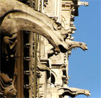
Recognisable Gothic characters, designed to dramatically spout water away from buildings.
A case study and a warning to would-be developers
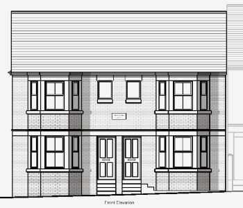
Creating four dwellings... after half a century of doing this job, why, oh why, is it so difficult?
Reform of the fire engineering profession
Fire Engineers Advisory Panel: Authoritative Statement, reactions and next steps.
Restoration and renewal of the Palace of Westminster
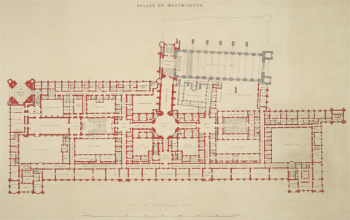
A complex project of cultural significance from full decant to EMI, opportunities and a potential a way forward.
Apprenticeships and the responsibility we share
Perspectives from the CIOB President as National Apprentice Week comes to a close.
The first line of defence against rain, wind and snow.
Building Safety recap January, 2026
What we missed at the end of last year, and at the start of this...
National Apprenticeship Week 2026, 9-15 Feb
Shining a light on the positive impacts for businesses, their apprentices and the wider economy alike.
Applications and benefits of acoustic flooring
From commercial to retail.
From solid to sprung and ribbed to raised.
Strengthening industry collaboration in Hong Kong
Hong Kong Institute of Construction and The Chartered Institute of Building sign Memorandum of Understanding.
A detailed description from the experts at Cornish Lime.
IHBC planning for growth with corporate plan development
Grow with the Institute by volunteering and CP25 consultation.
Connecting ambition and action for designers and specifiers.
Electrical skills gap deepens as apprenticeship starts fall despite surging demand says ECA.
Built environment bodies deepen joint action on EDI
B.E.Inclusive initiative agree next phase of joint equity, diversity and inclusion (EDI) action plan.
Recognising culture as key to sustainable economic growth
Creative UK Provocation paper: Culture as Growth Infrastructure.















Comments
https://www.designingbuildings.co.uk/wiki/Get_started_-_top_tips_and_help#Inserting_Images
https://www.designingbuildings.co.uk/wiki/Page_about_me