






Quality tools: fishbone diagram
Contents |
[edit] What is it?
Created by Kaoru Ishikawa in the 1960s, the Fishbone diagram (cause and effect diagram) is a visual tool that shows the potential relationship between a topic (output – effect) and the various factors (inputs – causes) related to it. The diagram resembles the skeleton of a fish as the main causal categories are drawn as ‘bones’ attached to the spine of the fish.

[edit] When and how can I use it?
This tool encourages team participation and is useful in brainstorming. It can be used any time when the cause of a problem is unknown, such as a product defect or issues in the manufacturing or management process. The problem statement and potential categories of causes allow multiple categories of causes to be explored. It can be used as a planning tool to assure that all inputs necessary for a desired outcome have been identified. It can also be used to consider what went right and why during a ‘lessons learned’ exercise at the end of a project.
[edit] Steps
To show the relationships between the cause and effect, and to form a hierarchy of events, the potential causes are arranged based on their level of detail. These are the typical main categories: materials, equipment, people, environment, methods (MEPEM) and sometimes measurement. Facilities, technologies, policies, and practices could be other categories to consider.
1 On the far right side of the diagram write the problem statement. This may be the actual problem or it may be a symptom – at this point you’re not exactly sure and the effect may be refined as more information emerges.
2 Draw a long horizontal arrow pointing to the box. This arrow will serve as the backbone from which further major and minor causes will be categorised and related.
3 Identify potential causes and group them into major categories along the ‘bones’ of the fishbone diagram. Major categories can be established using brainstorming. At this point you shouldn’t be concerned if there is disagreement about whether a category holds the potential cause or not. Just include all of them. Make sure to leave enough space between the major categories on the diagram so that you can add the minor detailed causes.
4 Once you and your team have listed all possible causes you then have the information needed to identify and agree the most likely causes and decide which to investigate further.
[edit] Did you know?
The Fishbone diagram is one of the seven basic quality tools. The Project Management Institute references these seven tools in A Guide to the Project Management Body of Knowledge as an example of a set of general tools useful for planning or controlling project quality.
This article was produced by Jo Dovey and Brian Rutter on behalf of the Chartered Quality Institute and published in Quality World, January 2019.
--ConSIG CWG 18:24, 26 May 2019 (BST)
[edit] Related articles on Designing Buildings Wiki
Featured articles
Check out some of the best features and news from Designing Buildings as well as key stories from around the web.
CIOB publishes free template to help assess and manage risks.
ECA's reflections on Party Conference season

Burnham wants to be confident of winning before asking for a fresh mandate.
New Chief Construction and Scientific Adviser
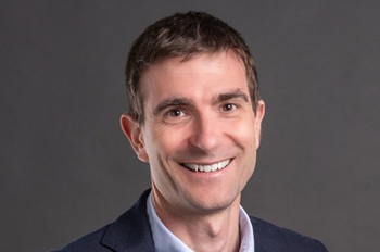
Sergio Cavalaro, Professor of Infrastructure Systems at Loughborough University.
Building safety levy for England

CIAT publish estimator tool for members.
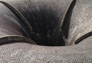
Water sector faces a growing crisis that could slow the delivery of vital infrastructure.
Undervaluing our industrial past
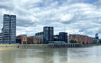
Heritage value changes as taste for building styles changes.
Changing expectations around competence and compliance

New information sheet from CIAT.
Grenfell investigation files passed to CPS
Angela Rayner apologises on behalf of the British state.

Electrical contractors need to understand the practical implications.
The real barrier to getting more value from digital technology.
Your guide to The Construction Reset at UKCW Birmingham.

Accommodating the Victorian and Edwardian working woman. Book review.