


CAD layer
Contents |
[edit] Using layers in CAD for OVERLAY drafting:
This is a personal view challenging the regular explanations of CAD layers. It includes references to MYCADKEYS and MYCADLAYERS that are proprietary products and thus should be read in conjunction with other “authorized” explanations.
[edit] What is a CAD Layer?
The common metaphor for a layer “clear plastic sheet” although initially helpful is overly simplistic tending to lodge in a drafter’s mind forever hampering a fuller understanding of the true value of layers. Most tutorials concentrate on how to use layer commands saying little about Layer Naming Standards or how to use layers effectively and rarely about using potentially faster keyboard commands rather than slow and sometimes visually overwhelming layer manager dialogues.
The first thing to say about layers is that “LAYERS” is not the best word to describe them. Forget layers as anything physical (transparent sheets) and think instead of “LAYERNAME” as a label for a list of object properties. One should think of “assigning” the property of layername to an object rather than assigning an object to a layer. Although it is common to refer to drawing “on” a layer, typically done by setting a layer to be the current layer and about “moving” objects from one layer to another in reality this is assigning a different layername as a property to object(s).
[edit] Why use Layers?
In addition to the regular benefits of using layers, described elsewhere, most Standards typically use layernames to identify project properties such as the nature, function and location of objects within a project allowing a complete project to be drawn coincidently and then separated function from function by viewing and plotting appropriate layers. Another important feature of layers is the ability to assign a color, line-type and line-thickness BYLAYER. This is commonly done in preference to assigning BYOBJECT since it makes changing much easier by globally redefining the layer’s properties.
[edit] What is MYCADLAYERS?
MYCADLAYERS is a layer management program offering a custom designed Layer Naming Standard. (Custom designed Standard how can that be? you might ask.). MYCADLAYERS is simpler, shorter, more meaningful and easier to use than most layer standards yet it complies with the principles of all major international standards.
MYCADLAYERS completely replaces normal CAD dialogue layer naming and management procedures, such as LAYMAN, dramatically reducing operator effort. How much? Not really sure because it is so long since I have needed to use slow and clumsy layer management dialogues but my guess is that for me MYCADLAYERS reduces the task to less than one quarter of the time required by conventional means while at the same time ensuring accuracy of naming and adherence to the code.
MYCADLAYERS is supported by a range of automated commands that ensure ease of use such that layer visibility can be automatically filtered for any one of seven properties including drawing type, view-point and ID (level, section etc.). In this manner an entire set of drawings; plans, elevations, sections etc. can be created within a single model single file.
MYCADLAYERS’ layernames are made up of twelve characters in seven fields but are nevertheless shorter than national Standards. An important difference in MYCADLAYERS is that they include fields for color and line-type that in addition to providing additional layer separation allow automatic assignment of color and line-type upon layer creation. In spite of the apparent complexity of MYCADLAYERS it is never necessary to use graphical layer manager layer tables except for interrogating drawings from other sources.
[edit] What are MYCADZONES?
MYCADLAYERS not only permits Coincident Overlay Modeling but is designed specifically to support the creation of multiple WORKZONES within a single model. WORKZONES can be defined not just by drawing-type but also by project view-point and view-ID. A number of commands are provided for filtering layernames to reveal the desired WORKZONES such as “electrical floor plan level 1” or “brickwork plan level 3” and so on. Entire WORKZONES can be copied from one level to another automatically changing the view-ID field to another level. WORKZONES can be automatically resolved separately or in any combination for editing or printing. This is especially beneficial for checking component alignments and clashes.
[edit] So how does oneI get to use MYCADLAYERS?
Log into https://mycadkeys. Have a look at the whole program, especially MYCADLAYERS. Decide if you would like to try MYCADKEYS. If so go to “Install” for a free copy of the program.
You must sign in or register to edit or comment on an article
Return to Talk:CAD layer.
Featured articles and news
RTPI leader to become new CIOB Chief Executive Officer

Dr Victoria Hills MRTPI, FICE to take over after Caroline Gumble’s departure.
Social and affordable housing, a long term plan for delivery

The “Delivering a Decade of Renewal for Social and Affordable Housing” strategy sets out future path.
A change to adoptive architecture
Effects of global weather warming on architectural detailing, material choice and human interaction.

The proposed publicly owned and backed subsidiary of Homes England, to facilitate new homes.

How big is the problem and what can we do to mitigate the effects?
Overheating guidance and tools for building designers

A number of cool guides to help with the heat.
The UK's Modern Industrial Strategy: A 10 year plan

Previous consultation criticism, current key elements and general support with some persisting reservations.
Building Safety Regulator reforms

New roles, new staff and a new fast track service pave the way for a single construction regulator.
Architectural Technologist CPDs and Communications

CIAT CPD… and how you can do it!
Cooling centres and cool spaces
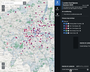
Managing extreme heat in cities by directing the public to places for heat stress relief and water sources.
Winter gardens: A brief history and warm variations

Extending the season with glass in different forms and terms.
Restoring Great Yarmouth's Winter Gardens

Transforming one of the least sustainable constructions imaginable.
Construction Skills Mission Board launch sector drive

Newly formed government and industry collaboration set strategy for recruiting an additional 100,000 construction workers a year.
New Architects Code comes into effect in September 2025
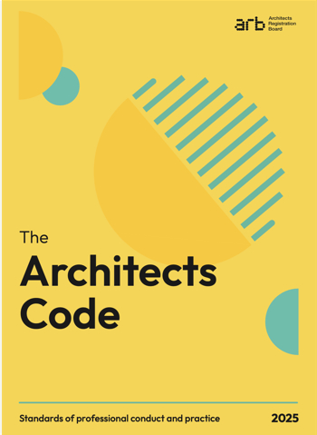
ARB Architects Code of Conduct and Practice available with ongoing consultation regarding guidance.
Welsh Skills Body (Medr) launches ambitious plan

The new skills body brings together funding and regulation of tertiary education and research for the devolved nation.
Paul Gandy FCIOB announced as next CIOB President

Former Tilbury Douglas CEO takes helm.
UK Infrastructure: A 10 Year Strategy. In brief with reactions

With the National Infrastructure and Service Transformation Authority (NISTA).